Method and apparatus for producing wound electrode assembly, and method for producing battery

Inactive Publication Date: 2011-01-20
TOYOTA JIDOSHA KK
View PDF4 Cites 10 Cited by
  • Summary
  • Abstract
  • Description
  • Claims
  • Application Information

AI Technical Summary

Benefits of technology

[0008]The inventor has developed the present invention in an attempt to provide a wound electrode assembl

Problems solved by technology

Various problems arise if the winding speed is increased or reduced at such a high rate.
If the tension decreases sharply, air is likely to be trapped in the wound strip materials, and the wound electrode assembly becomes soft.

Method used


Image

  • Method and apparatus for producing wound electrode assembly, and method for producing battery
  • Method and apparatus for producing wound electrode assembly, and method for producing battery
  • Method and apparatus for producing wound electrode assembly, and method for producing battery

Examples


Embodiment Construction

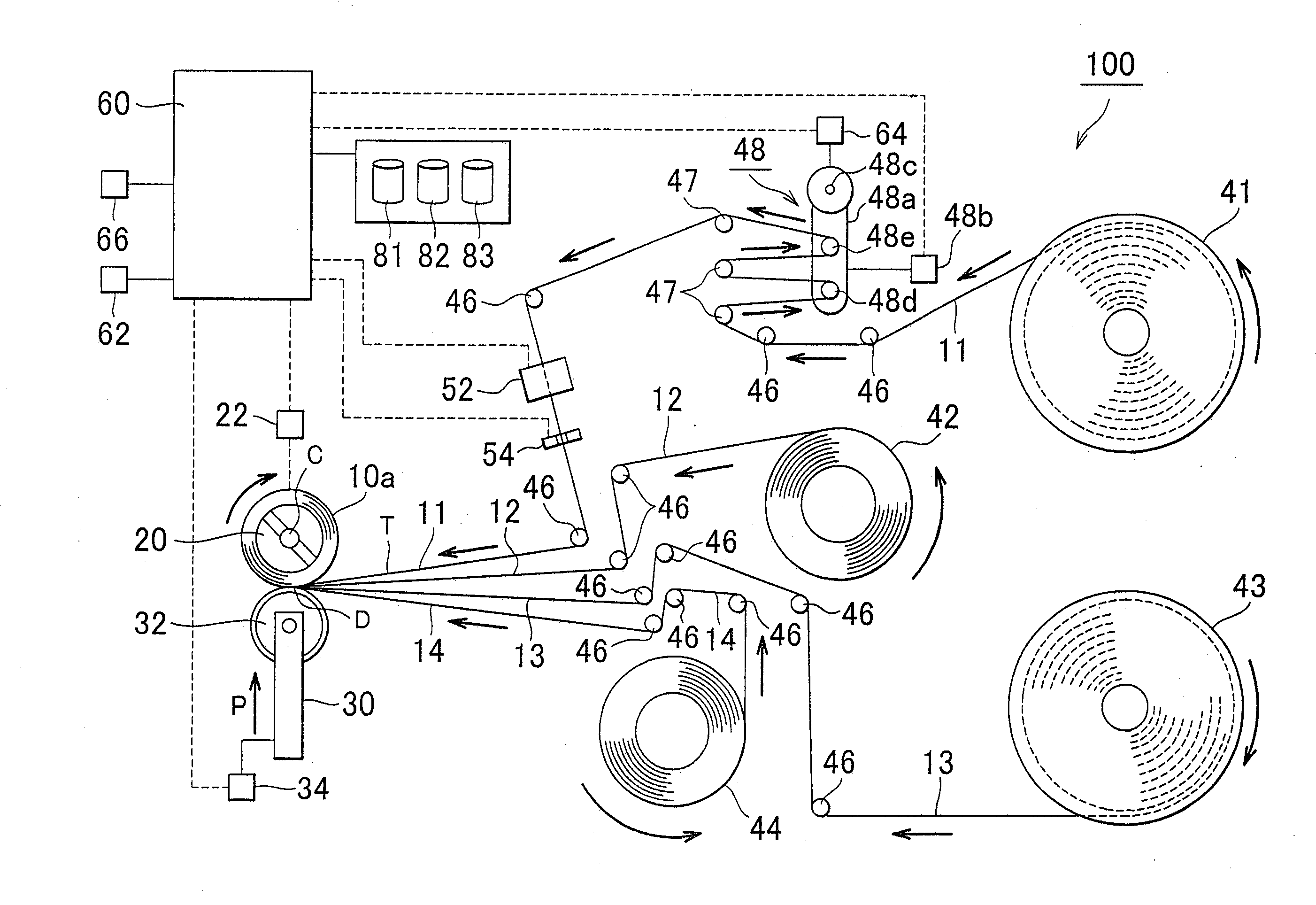
[0029]One example of method for producing a wound electrode assembly according to one embodiment of the invention and one example of apparatus that implements the method of production will be described with reference to the drawings. In the following description, electrode strips and separator strips will be generally called “strip material” when appropriate.

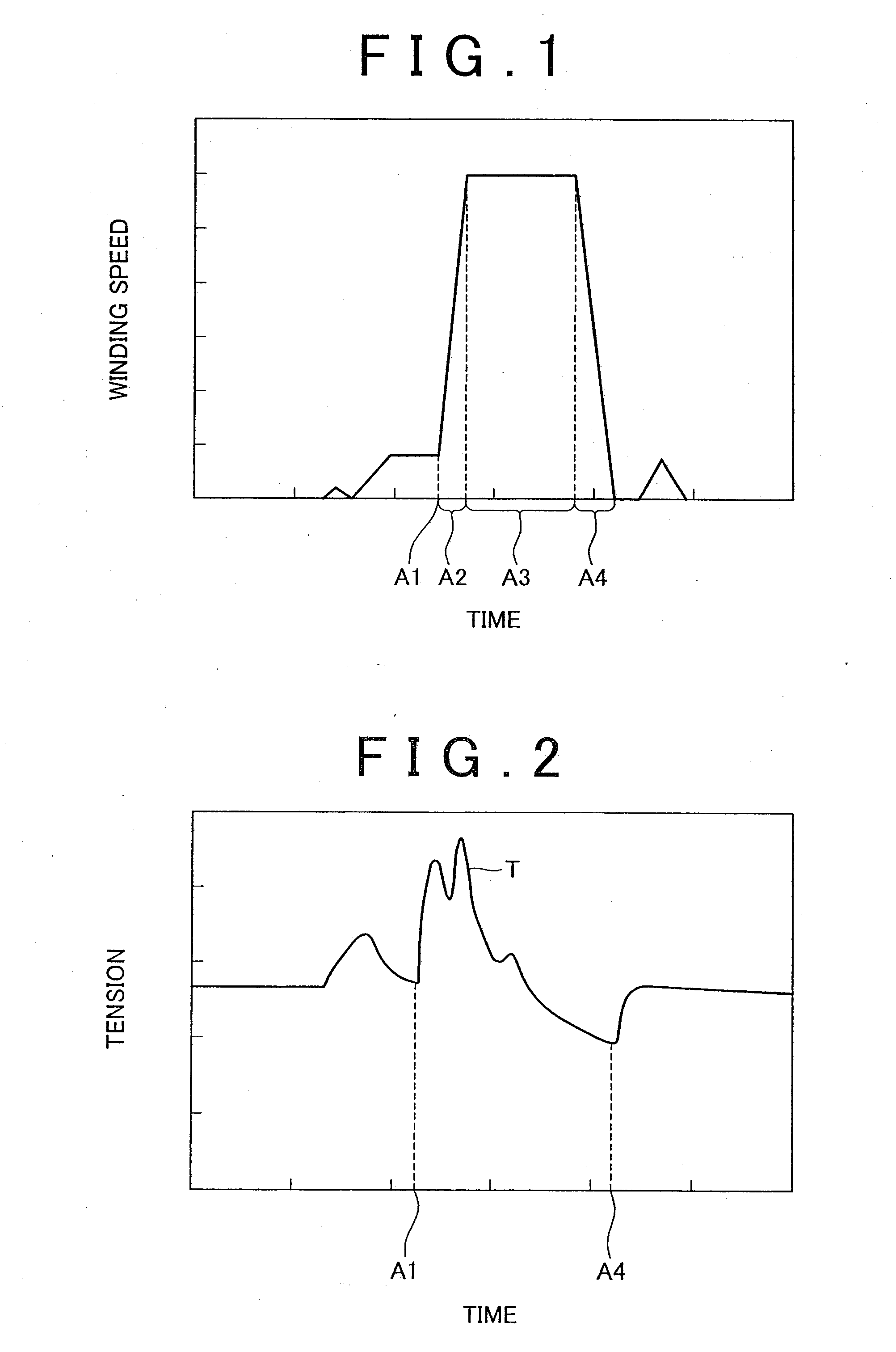
[0030]In the case where the winding speed is increased so as to shorten winding time (i.e., a length of time required to wind up strip materials), the wound electrode assembly does not provide stable or uniform hardness even when the electrode strips and separator strips are wound while being pressed by a pressing member against a take-up shaft. The inventor of the present invention considers sharp increase and decrease of the winding speed as a cause of the instability in the hardness. More specifically, in order to shorten the winding time, the winding speed is sharply increased (A2) from the beginning of winding (A1), so as t...


PUM

PropertyMeasurementUnit
Forceaaaaaaaaaa
Diameteraaaaaaaaaa
Widthaaaaaaaaaa

Abstract

A method for producing a wound electrode assembly includes steps of overlaying electrode strips (11, 13) and separator strips (12, 14) on each other, and winding the electrode strips (11, 13) and the separator strips (12, 14) on a take-up shaft (20) while pressing a pressing member (30) against the electrode strips and the separator strips. In the winding step, the pressing force of the pressing member (30) is increased with decrease in a tension T applied to at least one of the electrode strips (11, 13) and the separator strips (12, 14).

Description

BACKGROUND OF THE. INVENTION[0001]1. Field of the Invention[0002]This invention relates to method and apparatus for producing a wound electrode assembly by overlaying and winding electrode strips and separator strips.[0003]2. Description of the Related Art[0004]An example of the method for producing a wound electrode assembly is described in Japanese Patent Application Publication No. 2007-142351 (JP-A-2007-142351). An apparatus disclosed in this publication is arranged to take up elements while pressing a pressure roller (corresponding to a pressing member) against elements (substantially corresponding to electrode strips and separator strips) that are being wound, so as to make the outside diameter and hardness of the wound elements stable or uniform. In this apparatus, while the elements are wound into a roll, the pressure roller is pressed against the elements toward a core of the roll, so as to discharge air trapped in clearances between the elements. However, there is no speci...

Claims


Application Information

Patent Timeline
IPC IPC(8): H01M4/04B65H23/00B65H18/26B65H23/195B65H39/16H01M10/04H01M10/0587
CPCB65H39/16B65H2511/20H01M10/0409H01M10/0431H01M10/0525H01M10/0587B65H2801/72Y10T29/49115Y02E60/10Y02P70/50B65H2511/14B65H2220/02H01M2220/20
Inventor TSUCHIYA, KENJITAKEDA, MASATAKA
Owner TOYOTA JIDOSHA KK
Why Eureka
Try Eureka