Distillation device

Inactive Publication Date: 2011-01-20
JOST 50 EVELYN +1
View PDF6 Cites 0 Cited by
  • Summary
  • Abstract
  • Description
  • Claims
  • Application Information

AI Technical Summary

Benefits of technology

[0010]In the case of the pipes, it preferably concerns pipes with a circular cross section, but pipes with a rectangular or other cross section are also possible. Inside the pipes, moreover, provision can be made for elements which influence the flow, especially ensuring a continuous mixing-through while flowing, so that in the liquid which is to be distilled a temperature profile which is as uniform as possible is established. The design of the distillation sections as pipelines enables the provision of a large heat transfer surface area as a result of a large pipeline surface. Furthermore, as a result of the flowing of the medium which is to be distilled in the pipeline a good mixing-through ensues and consequently a more uniform temperature profile in the flowing medium than in the case of a vessel with standing liquid.
[0012]Between the first distillation section and the second distillation section, provision is especially preferably made for a feed pipeline for the admixing of a degassing accelerator. Since some of the liquid which is to be separated has already been removed in the first distillation section, less degassing accelerator is required. The degassing accelerator, moreover, enables improved separation of the liquid which is to be separated. Furthermore, the degree of purity of the part of the liquid which is to be separated is increased and the remaining residue minimized.
[0014]In order to lower the temperature which is required for distillation, and therefore to reduce the necessary expenditure of energy, the distillation device can be especially preferably operated under a negative pressure.
[0015]The distillation sections are especially preferably arranged in a heatable tank. The tank in this case can define the heating chamber and can even be thermally insulated on the outside, wherein a temperature-controlled medium, such as hot water, hot oil or water vapor, can be supplied from outside. This enables a uniform temperature distribution inside the tank and therefore a uniform transfer of heat inside the tank.
[0020]Provision is especially preferably made for a plurality of gas outlet pipelines in the first distillation section. This enables a faster and better separation of the distilled component of the liquid. In the case of a coil-like configuration of the pipeline in the first distillation section, the gas outlet pipelines can be led upwards, extending inside the coil, so that a space-saving configuration results.
[0026]In the case of gases which are heavier, the gas collecting outlet pipeline is especially preferably arranged lower than the pipeline of the second distillation section. This enables a simple collecting and discharging of the gas.

Problems solved by technology

Known distillation devices of these types leave much to be desired.
In particular, the efficiency of the distillation devices leaves a lot to be desired.

Method used


Image

  • Distillation device
  • Distillation device
  • Distillation device

Examples


Embodiment Construction

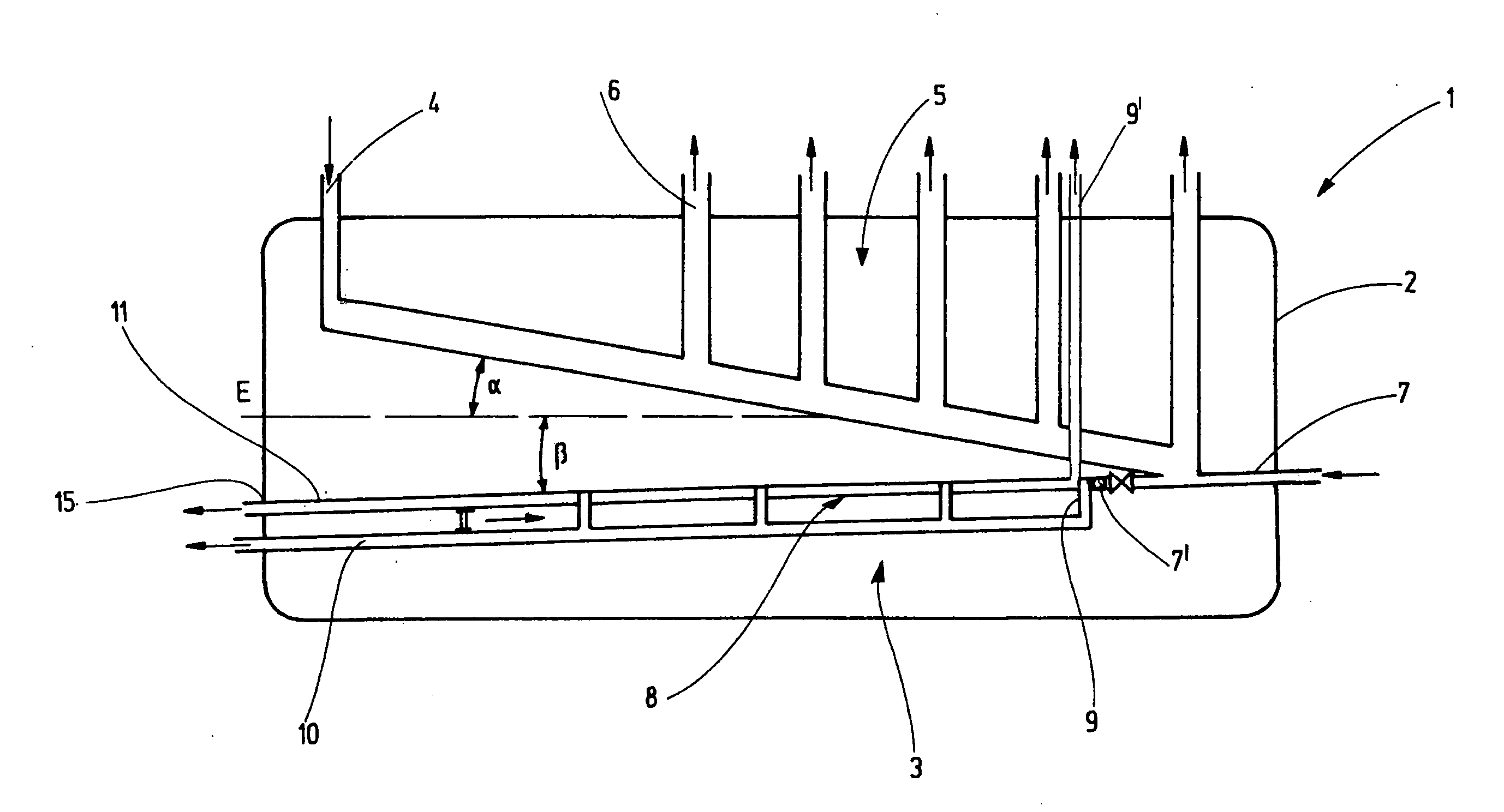
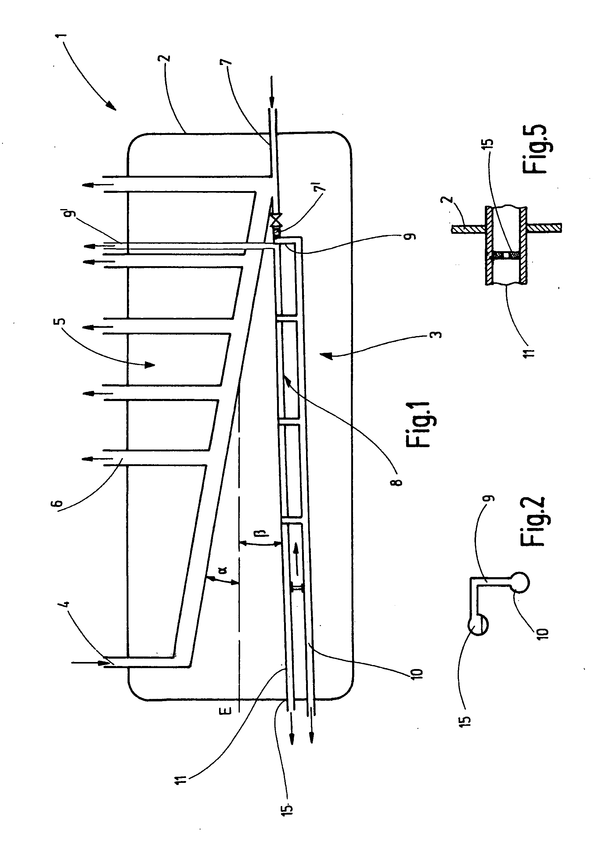
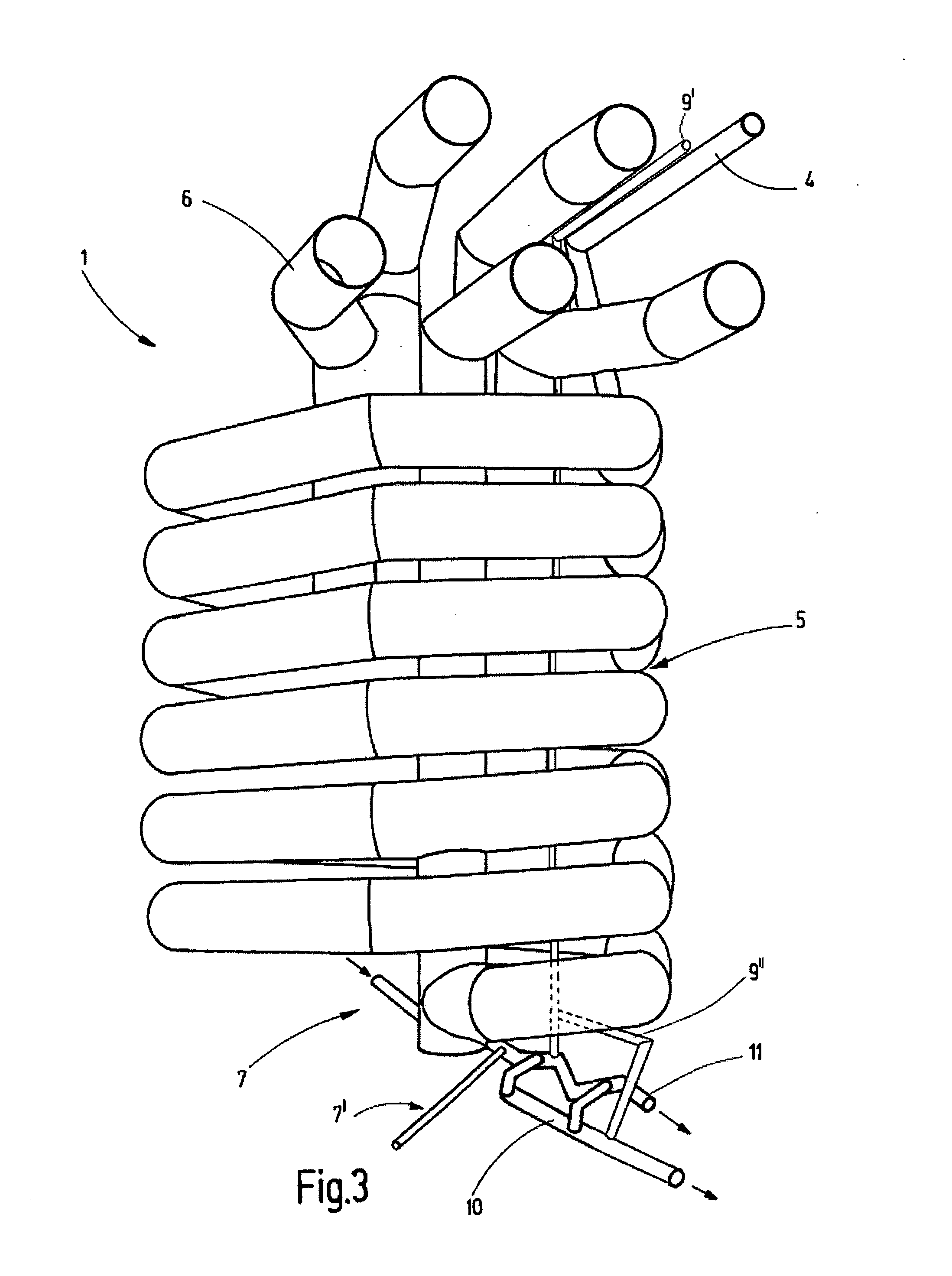
[0036]Referring to the drawings in particular, a distillation device 1 has a tank 2 which can be heated by means of a heating facility, which is not shown in more detail, in the present case by means of water vapor which is formed in a separately formed boiler and introduced into the tank 2, and also a pipeline arrangement 3 which is arranged in the tank 2, wherein for the pipeline arrangement 3 a multiplicity of supply and disposal pipelines are led into the tank 2 or led out of it as the case may be. The tank 2 is of a pressure-tight design and is well insulated. The pipeline arrangement 3 in the present case consists of copper pipes which have good heat conductivity.

[0037]The pipeline arrangement 3 has a distillation-medium inlet pipeline 4 into the tank 2, a continuing pipeline of a coil-like design, forming a first distillation section 5, with a significantly larger diameter than the inlet pipeline 4, various first gas outlet pipelines 6 which branch from the first distillation...


PUM


Abstract

A distillation device (1) includes at least one first distillation region (5) with at least one first gas outlet line (6) and at least one second distillation region (8) with at least one further gas outlet line (9, 9′). The distillation regions (5, 8) are connected to each other. The first distillation region (5) is formed by a first line, the second distillation region (8) by a second line, and both lines forming the distillation regions (5, 8) are connected to each other in a controllable way. The invention further relates to methods for operating such a distillation device (1).

Description

CROSS REFERENCE TO RELATED APPLICATIONS[0001]This application is a United States National Phase application of International Application PCT / EP2009 / 000103 and claims the benefit of priority under 35 U.S.C. §119 of German Patent Application 10 2008 005 861.0 filed Jan. 15, 2008, the entire contents of which are incorporated herein by reference.FIELD OF THE INVENTION[0002]The invention refers to a distillation device, as is used for distilling liquids, especially for separating liquid mixtures.BACKGROUND OF THE INVENTION[0003]DE 1 773 893 A discloses a multistage distillation device with a first evaporation vessel and a distillation column arranged upon this, an adjoining condenser, and also further evaporation vessels and associated condensers, wherein the condensers are connected in each case to the subsequent evaporation vessel, and the condenser of the last vessel has a drainage pipe. In this case, all further evaporation vessels are arranged annularly around the distillation colu...

Claims


Application Information

Patent Timeline
IPC IPC(8): B01D3/42B01D3/02
CPCB01D3/34B01D1/14
Inventor JOST, EVELYN
Owner JOST 50 EVELYN
Why Eureka
Try Eureka