Circuit arrangement and method for inductive energy transfer

a circuit arrangement and inductive energy technology, applied in circuit arrangements, inductances, electromagnetic wave systems, etc., can solve the problems of not being able to adjust multiple operating states, and being only weakly affected by the power consumption of charging stations

Active Publication Date: 2011-01-20
BRAUN GMBH
View PDF1 Cites 24 Cited by
  • Summary
  • Abstract
  • Description
  • Claims
  • Application Information

AI Technical Summary

Problems solved by technology

This solution is quite complicated because transmission means for the information from the secondary side to the primary side are required.
However, this variant is less suitable for adjusting multiple operating states b

Method used


Image

  • Circuit arrangement and method for inductive energy transfer
  • Circuit arrangement and method for inductive energy transfer
  • Circuit arrangement and method for inductive energy transfer

Examples


second embodiment

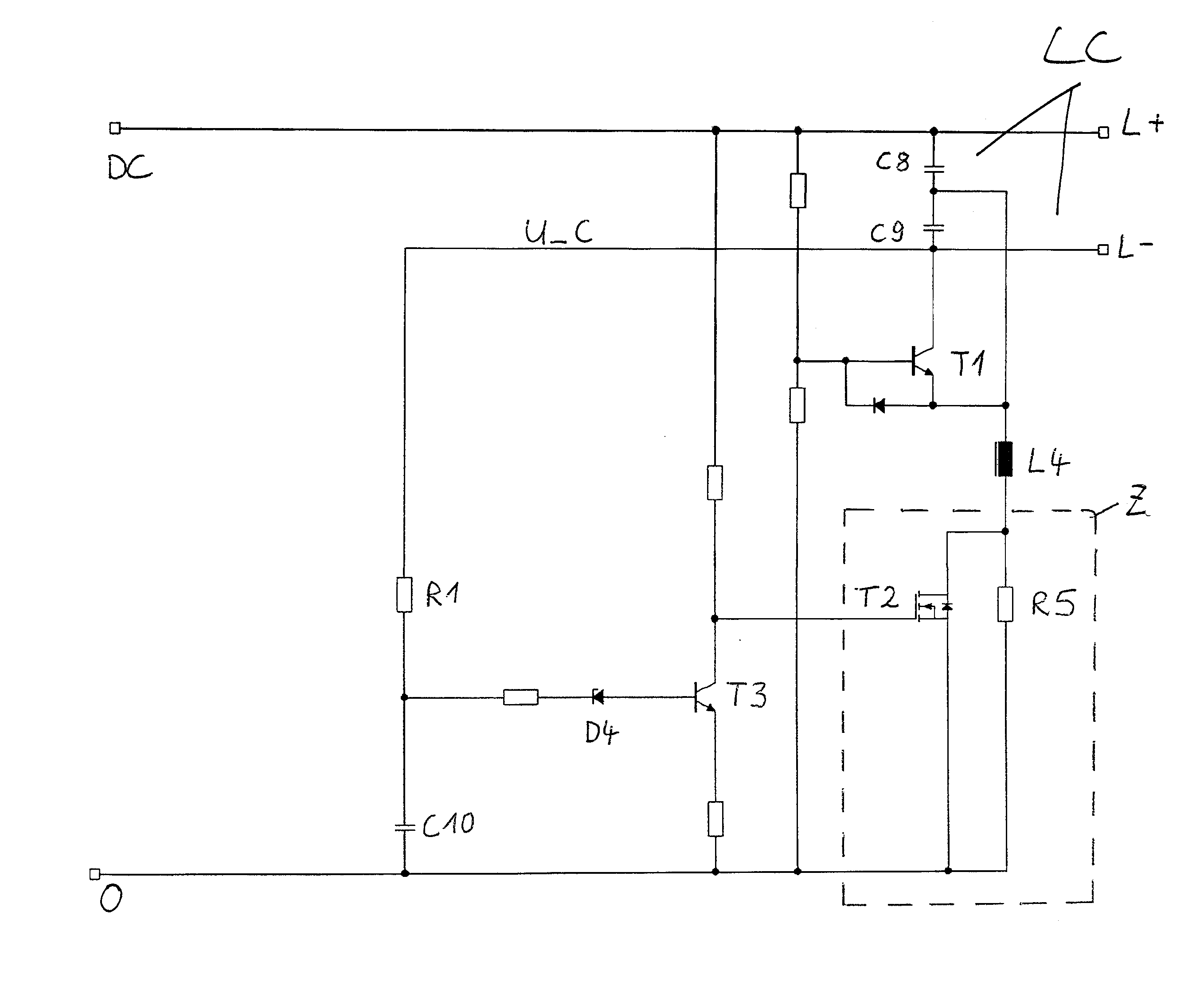
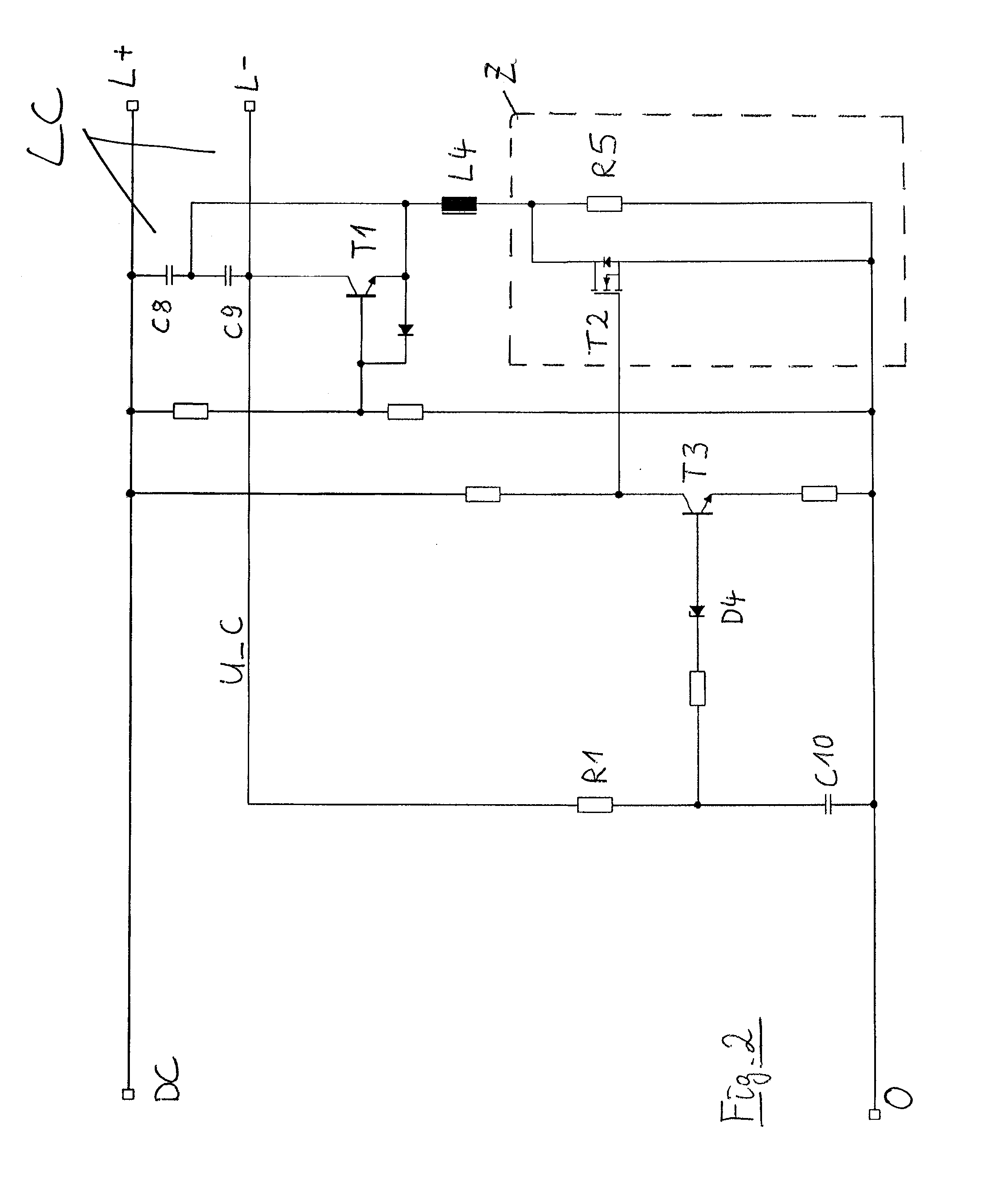
[0024]Instead of a Zener diode, a reference diode RD4 can be used as a comparator. FIG. 3 shows such a The collector potential of T1 is supplied via a diode D1 to the control terminal GND of the reference diode RD4. If the potential at the control terminal GND remains below an (internally set) reference voltage, the output OUT is low. The pnp-transistor T3 is conductive. The gate of the field effect transistor T2 is hereby connected with VDD; the potential is thus high. The field effect transistor T2 is conductive, such that energy can flow into the oscillator. If the potential at the control terminal GND exceeds the (internally set) reference voltage, the potential at the VDD terminal is connected through to the output OUT. The transistor T3 is hereby blocked. The potential at the gate of the field effect transistor T2 is low, such that the field effect transistor T2 is blocked. The energy feed into the oscillator is minimal.

third embodiment

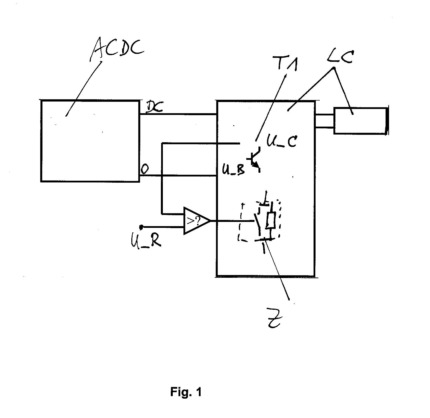
[0025]FIG. 4 shows the invention. Here the evaluation of the collector potential of T1 occurs by means of an operation amplifier OPAMP as a comparator. A comparison of the peak value of the collector voltage (i.e. the amplitude) with an average value of the collector voltage as a reference voltage U_R takes place by connecting the operation amplifier OPAMP. The reference voltage is adjusted via a voltage splitter comprising the resistors R4 and R5 and the capacitor C1. The peak value of the collector voltage is formed by the voltage splitter comprising the resistances R1, R2 and the diode D3 as well as the capacitor C2. If the peak value drops in relation to the average value, which corresponds to a higher load of the oscillator, the emitter resistance is reduced, such that more electrical energy is supplied again.

[0026]In the Colpitts oscillators in common base connection as they are shown in the Figures, instead of the collector voltage U_C, the voltage U_B at the base of the acti...


PUM


Abstract

A method and a circuit arrangement for the inductive transfer of energy with an oscillator and a device to detect the inductive load of the oscillator, and to modify a damping element in the oscillator depending on the load of said oscillator.

Description

CROSS REFERENCE TO RELATED APPLICATION[0001]This application is a continuation-in-part application of prior copending International Application No. PCT / IB2010 / 052587, filed Jun. 10, 2010, designating the United States.FIELD OF THE INVENTION[0002]The invention relates to a circuit arrangement and a method for inductive energy transfer for small electrical appliances, for example for an electric toothbrush or an electric shaver.BACKGROUND OF THE INVENTION[0003]Small, battery-operated electrical appliances are typically charged at an external charging station. Contactless charging stations that inductively transfer electrical energy from the charging station to the appliance are especially popular. For this purpose, an alternating magnetic field is generated in the charging station by an oscillator that has a coil element and a capacitor element, wherein the coil element simultaneously forms the primarily coil of an inductive transformer and the secondary coil of the transformer is arr...

Claims


Application Information

Patent Timeline
IPC IPC(8): H02J17/00
CPCH02J17/00H02J50/10H02J50/80H02M7/05
Inventor JUNG, PHILIPPLEPPER, JOACHIMLANGSDORF, JAN CHRISTIANHERZBERG, LUTZ RONALDHOHMANN, THOMAS
Owner BRAUN GMBH
Why Eureka
Try Eureka