Display device and liquid crystal display panel

a technology of liquid crystal display panel and display device, which is applied in the direction of static indicating device, optics, instruments, etc., can solve the problems of moving parts, unable to control who else may be watching, and giving a method by which the privacy function can be easily achieved

Active Publication Date: 2011-01-20
SHARP KK
View PDF31 Cites 14 Cited by
  • Summary
  • Abstract
  • Description
  • Claims
  • Application Information

AI Technical Summary

Benefits of technology

[0064]The average transmission function may vary smoothly across the whole of the wide range of viewing angles.
[0090]If any modification is to be performed for a group, the data value of at least one image element in the group may be increased while the data value of at least one other image element in the group may be decreased.

Problems solved by technology

This concept can be applied to many other types of devices where a user may which to view confidential information, but cannot control who else may be watching.
However none of them gives a method by which the privacy function can easily be switched off to allow viewing from a wide range of angles.
This method has the disadvantages that it requires moving parts that may fail or be damaged, and it adds significant bulk to the display.
They share the disadvantage that the light control film absorbs a significant fraction of the light incident upon it, whether the display is in the public or the private mode.
The display is therefore inefficient in its use of light.
Another disadvantage relates to the power consumption of such devices.
This is a disadvantage for displays that are used for most of the time in the public mode.
One disadvantage of this method relates to the difficulty and expense of manufacturing liquid crystal cells with an appropriate shape.
Another disadvantage is that, in the private mode, a ray of light may enter at an angle such that it passes first through the transparent material and then through part of a liquid crystal cell.
Such a ray will not be completely absorbed by the liquid crystal cell and this may reduce the privacy of the device.
However, when the display is viewed from a different angle, different pixels are viewed through the retarder elements and the image is corrupted.
However, due to unwanted diffraction of light from the display by the hologram, the colour of the image seen by viewers may be affected.
Furthermore, for applications using a touch screen mounted on the front of the display, the user's hand can block the illumination of the hologram and so reduce the effectiveness of the privacy mode.
However, this technique will only serve to modify the view angle characteristics of the display, and will not tend to hide the image at wide angles.
However, this method does not conceal displayed information as such when in the narrow mode, it only modifies the grey-scale mapping to distort the image.
This method has a number of drawbacks: firstly, the user must wear shuttered glasses in order to observe the correct image; secondly, image privacy can also be compromised by rapidly moving a toothed object across the view of the display and thus obscuring some parts of the cancelling image; and thirdly a ghost image can be observed as it is very difficult to design the two images to cancel perfectly.
However, this solution does inevitably affect the on-axis performance of the display in some degree, and the pattern visibility will disturb even the authorised user when using the display in the private mode.
Further, in practice, the patterning is not sufficient to provide an adequate level of privacy off-axis.
The imaging element described is not switchable, and consequently a device making use of this technology could not be switchable between public and private modes of operation.
However, the viewing angle of a single tilt domain of the VAN mode described is generally not sufficiently narrow to provide a good privacy mode.
However, this narrow mode is fixed, and there is no wide viewing mode.

Method used


Image

  • Display device and liquid crystal display panel
  • Display device and liquid crystal display panel
  • Display device and liquid crystal display panel

Examples


first embodiment

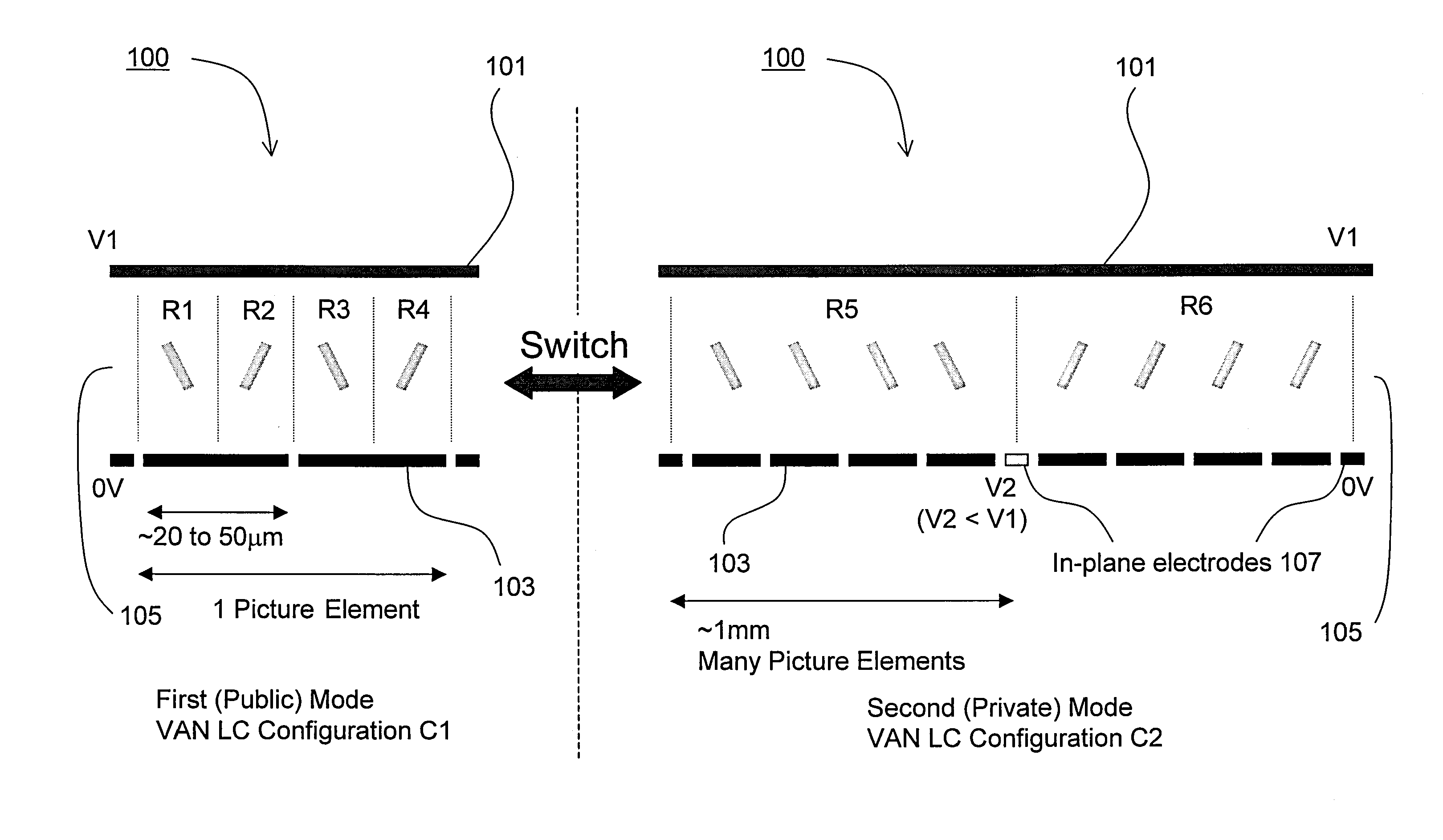
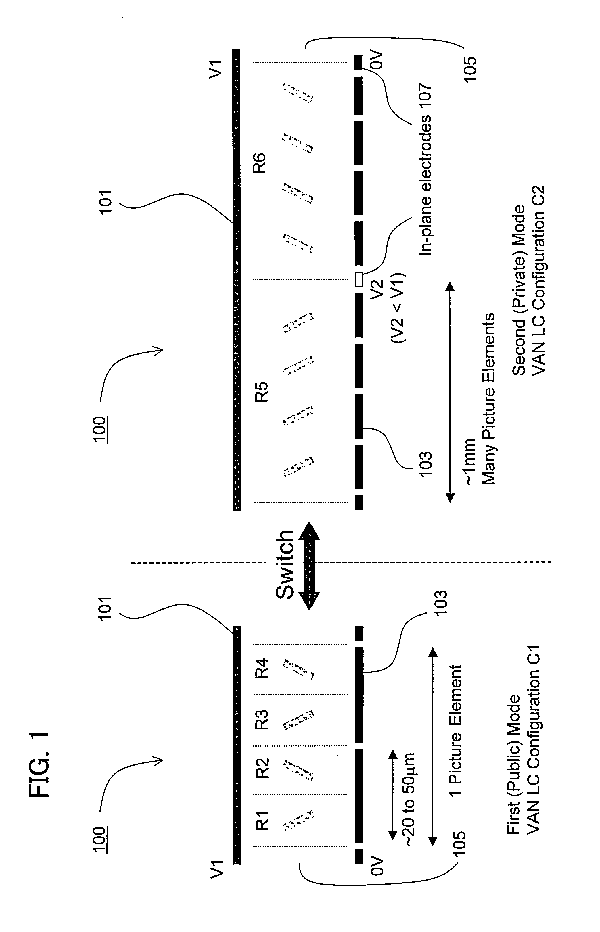
[0163]FIG. 1 illustrates a display device incorporating a liquid crystal display panel 100 according to the present invention. The liquid crystal display panel 100 displays an image by spatial light modulation, using opposed electrodes 101 and 103 disposed across a layer of liquid crystal material 105. The electrode 103 is segmented so as to enable switching of the liquid crystal into two or more different orientations within a single picture element. Within a single picture element the same voltage is applied to all areas of the segmented electrode 103. Preferably several regions of the two or more different orientations are formed within a single picture element. Switching into the different orientations is controlled by the fringing electric fields produced at the edges of the segmented electrode 103. Alternatively other methods of producing fringing electric fields, such as protrusions on the electrode surface, may be used.

[0164]As explained in more detail below, the liquid crys...

second embodiment

[0178]the present invention, also making use of an in-panel liquid crystal switching technique to achieve switching between a public and private mode, will now be described with reference to FIGS. 3 to 12.

[0179]FIG. 3 is a block diagram illustrating an image display system 1 for use in explaining a second embodiment of the present invention. The image display system 1 comprises an image processor 10, a display controller 20 and a display device 30. The display device comprises a display panel 32 and a non-linear component 34. A liquid crystal display panel 200 according to the second embodiment is illustrated in FIG. 4, and is intended to replace the display panel 32 and a non-linear component 34 of FIG. 3, as will be described below. Referring to FIG. 3, an original image I is to be displayed on the display panel 32 of the display device 30. The original image I is represented by a plurality of image elements, which may correspond to pixels of the display panel 32 or sub-pixels of ...

fourth embodiment

[0225]A fourth embodiment will be described with reference to FIGS. 14(A) to 17. In this embodiment, switchable privacy is achieved using an LC mode which has two voltage ranges, denoted in FIGS. 14(A) and 14(B) as ranges A and B, with similar greyscale variation on axis but a single voltage range, denoted as A in FIGS. 14(A) and 14(B), with normal greyscale variation off axis. In the public mode, the voltage range A having normal greyscale variation both on axis (FIG. 14(A)) and off axis (FIG. 14(B)) is used and good image quality is seen at all viewing angles. In the private mode, some of the pixels achieve the desired greyscale on axis (FIG. 14(A)) using the first voltage range A and other pixels achieve the same greyscale on axis (FIG. 14(A)) using the second voltage range B. Pixels that use the first voltage range A will appear normal both on and off axis (see pixels in the example image on the right-hand side of FIGS. 14(A) and 14(B) respectively that are linked by an arrow to...


PUM


Abstract

A display device is provided that comprises a liquid crystal display panel for displaying an image by spatial light modulation, and circuitry for switching liquid crystal in the panel between having a first configuration in a first mode to cause an image displayed using the panel to be discernible from a wide range of viewing angles, and having a second configuration in a second mode to cause an image displayed using the panel to be discernible substantially only from within a narrow range of viewing angles. Several types of display panel to achieve such in-panel switching between public and private viewing modes are disclosed.

Description

[0001]This Nonprovisional application is a divisional of Nonprovisional patent application Ser. No. 11 / 428,883 filed Jul. 6, 2006, which claims priority under 35 U.S.C. §119(a) on Patent Applications No. 0513971.2 and No. 1513968.8 filed in U.K. on Jul. 8, 2005, the entire contents of which are hereby incorporated by reference.FIELD OF THE INVENTION[0002]The present invention relates to a display device and a liquid crystal display panel for use in a display device.BACKGROUND OF THE INVENTION[0003]Electronic display devices, such as monitors used with computers and screens built in to telephones and portable information devices, are usually designed to have a viewing angle as wide as possible, so that they can be read from as many viewing positions as possible.[0004]However, there are some situations where it is useful to have a display that is visible from only a narrow range of angles. For example, where a person is reading a confidential or private document on the display of a mo...

Claims


Application Information

Patent Timeline
Patent Type & Authority Applications(United States)
IPC IPC(8): G09G5/00G09G3/36
CPCG02F1/134363G02F2001/134381G09G2320/068G09G2300/0434G09G2320/0271G09G3/3611G02F1/134381G02F1/133G02F1/1337
Inventor GASS, PAUL ANTONYKEAN, DIANA ULRICHSMITH, NATHANWYNNE-POWELL, THOMAS MATHEWEVANS, ALLANBROUGHTON, BENJAMIN JOHN
Owner SHARP KK
Why Eureka
Try Eureka