
Lens unit, image capturing lens, image capturing device and portable terminal

a technology of image capturing lens and lens body, which is applied in the field of lens body, image capturing lens, image capturing device and portable terminal, can solve the problems general negative change in refractive index with respect to temperature change, and general performance decline, so as to reduce the occurrence of image surface curvature, suppress defocusing, and immunize the effect of deterioration of performance in the entire lens system

Inactive Publication Date: 2011-01-20
KONICA MINOLTA OPTO
View PDF9 Cites 18 Cited by
  • Summary
  • Abstract
  • Description
  • Claims
  • Application Information

AI Technical Summary

Benefits of technology

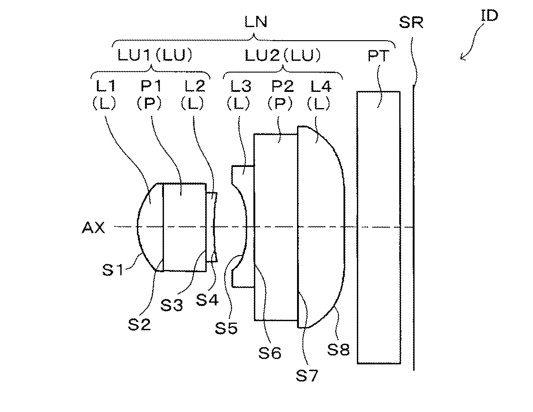
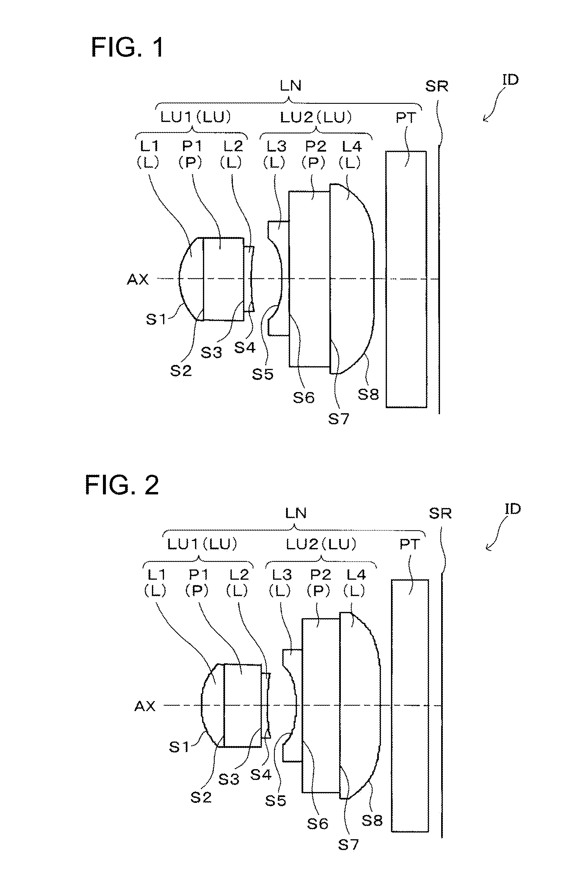
[0024]According to the present invention, the lens portion undergoes a change in the surface shape opposite to those of a conventional resin lens wherein a change in the paraxial image point position of the entire lens system caused by a change in the surface shape of the lens portion whose paraxial radius is reduced with temperature change by the difference in linear expansion coefficient between the lens holding plate and lens portion are contrary to a change in the paraxial image point position of the entire lens system caused by a change in the refractive index of the lens portion due to temperature change. This suppresses the defocusing caused by the change in the paraxial image point position of the entire lens system resulting from temperature change. Further, when the conditional expressions (1) and (2) are satisfied at the same time, defocusing due to temperature rise is suppressed and, at the same time, the occurrence of image surface curvature is reduced, whereby the deterioration of performances in the entire lens system can be immunized.

Problems solved by technology

However, in the resin lens, a change in the refractive index with respect to temperature change is generally negative.
Accordingly, serious defocusing from the design level is caused by the operation temperature and the performance is deteriorated.
This will result in defocusing, hence, deterioration in performances.

Method used


Image

  • Lens unit, image capturing lens, image capturing device and portable terminal
  • Lens unit, image capturing lens, image capturing device and portable terminal
  • Lens unit, image capturing lens, image capturing device and portable terminal

Examples


example 1

See FIG. 10

[0133]Unit mm

[0134]

[0135]Si r d n vd

[0136]1* 0.7745 0.295 1.48000 61.00

[0137]2 (stop) ∞ 0.500 1.54348 63.60

[0138]3 ∞ 0.085 1.58700 31.00

[0139]4* 2.8911 0.39064

[0140]5* −1.7226 0.085 1.58700 31.00

[0141]6 ∞ 0.500 1.59759 59.11

[0142]7 ∞ 0.532 1.58700 31.00

[0143]8* 15.1183 0.651

[0144]

[0145]Surface S1

[0146]K=−1.76E−01,

[0147]A=−6.72E−03, B=2.76E−01, C=−9.47E−01, D=1.81E+00

[0148]Surface S4

[0149]K=−1.01E+02

[0150]A=6.27E−01, B=−8.58E−01, C=9.68E−01, D=1.26E+01

[0151]Surface S5

[0152]K=7.53E+00

[0153]A=−4.09E−01, B=−1.22E+00, C=6.53E+00, D=−2.22E+01

[0154]Surface S8

[0155]K=−2.70E+03

[0156]A=−1.36E−01, B=−3.12E−02, C=2.08E−02, D=−1.29E−02

example 2

See FIG. 11

[0157]Unit mm

[0158]

[0159]Si r d n vd

[0160]1* 0.7737 0.296 1.47512 61.00

[0161]2 (stop) ∞ 0.500 1.54345 63.60

[0162]3 ∞ 0.085 1.58176 31.00

[0163]4* 2.8794 0.391

[0164]5* −1.7165 0.085 1.58176 31.00

[0165]6 ∞ 0.500 1.59756 59.11

[0166]7 ∞ 0.534 1.58176 31.00

[0167]8* 15.6569 0.697

[0168]

[0169]Surface S1

[0170]K=−1.51E−01,

[0171]A=−1.60E−02, B=2.80E−01, C=−9.50E−01, D=1.80E+00, E=0.00E+00

[0172]Surface S4

[0173]K=−1.01E+02,

[0174]A=6.30E−01, B=−8.60E−01, C=9.70E−01, D=1.30E+01, E=0.00E+00

[0175]Surface S5

[0176]K=7.51E+00,

[0177]A=−4.10E−01, B=−1.20E+00, C=6.50E+00, D=−2.20E+01, E=0.00E+00

[0178]Surface S8

[0179]K=−2.11E+03,

[0180]A=−1.40E−01, B=−2.50E−02, C=1.80E−02, D=−1.30E−02, E=−7.00E−10

example 3

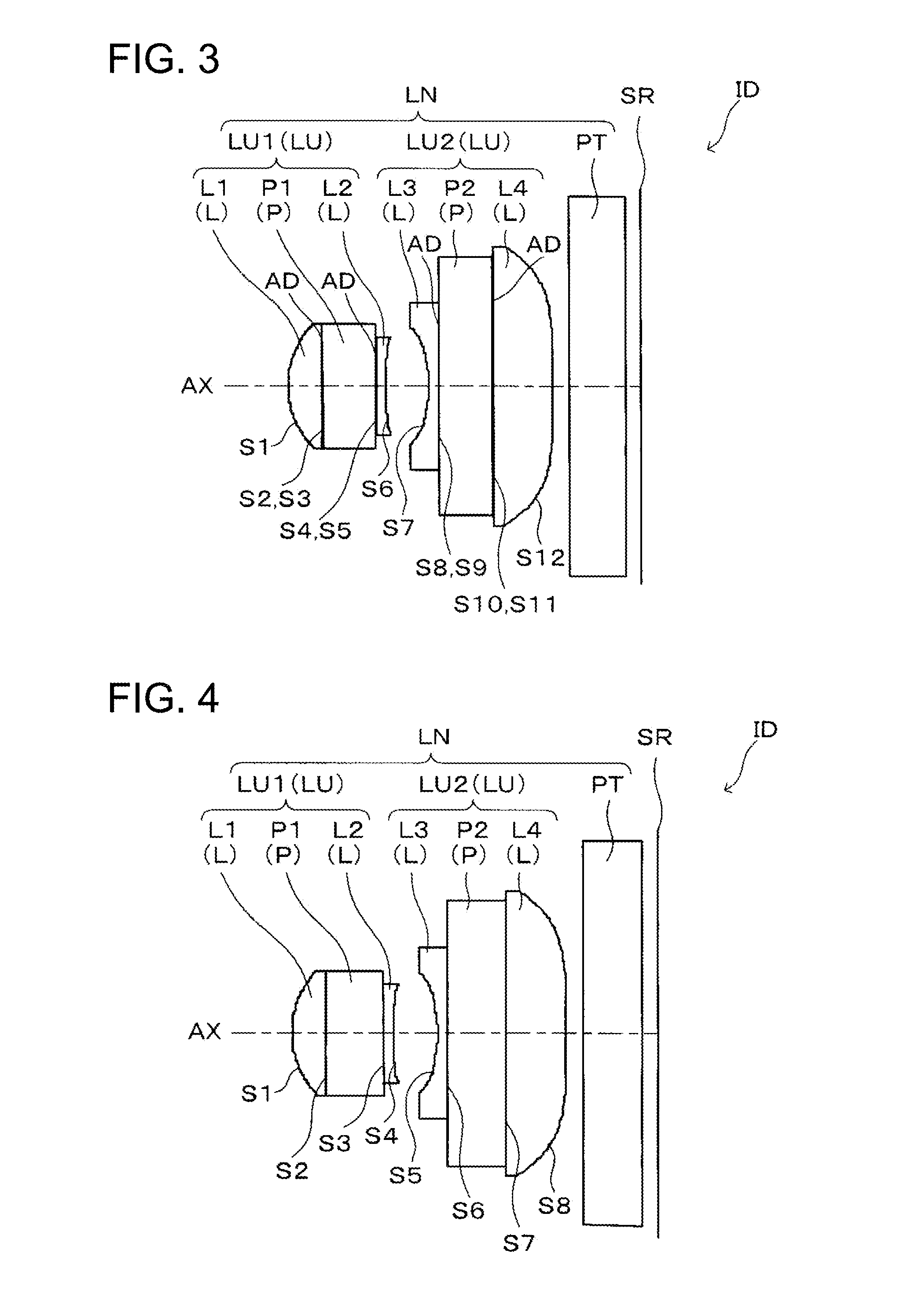
See FIG. 12

[0181]Unit mm

[0182]

[0183]Si r d n vd

[0184]1* 0.7737 0.286 1.47512 61.00

[0185]2 ∞ 0.010 1.47800 61.00

[0186]3 (stop) ∞ 0.500 1.54345 63.60

[0187]4 ∞ 0.010 1.47800 61.00

[0188]5 ∞ 0.075 1.58176 31.00

[0189]6* 2.8794 0.391

[0190]7* −1.7165 0.065 1.58176 31.00

[0191]8 ∞ 0.010 1.47800 61.00

[0192]9 ∞ 0.500 1.59756 59.11

[0193]10 ∞ 0.010 1.47800 61.00

[0194]11 ∞ 0.534 1.58176 31.00

[0195]12* 15.6569 0.697

[0196]

[0197]Surface S1

[0198]K=−1.51E−01,

[0199]A=−1.60E−02, B=2.80E−01, C=−9.50E−01, D=1.80E+00, E=0.00E+00

[0200]Surface S6

[0201]K=−1.01E+02,

[0202]A=6.30E−01, B=−8.60E−01, C=9.70E−01, D=1.30E+01, E=0.00E+00

[0203]Surface S7

[0204]K=7.51E+00,

[0205]A=−4.10E−01, B=−1.20E+00, C=6.50E+00, D=−2.20E+01, E=0.00E+00

[0206]Surface S12

[0207]K=−2.11E+03,

[0208]A=−1.40E−01, B=−2.50E−02, C=1.80E−02, D=−1.30E−02, E=−7.00E−10


PUM

PropertyMeasurementUnit
lengthaaaaaaaaaa
refractive indexaaaaaaaaaa
temperatureaaaaaaaaaa

Abstract

A lens unit LU in which a lens portion L is formed at least on either a light-receiving surface or a light-emitting surface of a lens holding plate P, wherein a difference in coefficients of linear expansion of the lens holding plate P and the lens portion L is used to suppress mis-focusing by causing changes in a paraxial image point position of the entire lens system due to changes in the surface shape of the lens portion L which accompany temperature changes, and changes in the paraxial image point position of the entire lens system due to changes in the refraction index to cancel each other out. Furthermore, deterioration of performance of the entire lens system caused by rising temperature is suppressed by satisfying a predetermined conditional expression.

Description

FIELD OF THE INVENTION[0001]The present invention relates to a lens unit including a lens holding plate and lens portion, an image capturing lens including the lens unit, an image capturing device including the image capturing lens, and a portable terminal including the image capturing device.BACKGROUND[0002]In recent years, an image capturing device of a compact and slim configuration has come to be mounted on a portable terminal as an electric device of compact and slim configuration such as a cellular mobile telephone and PDA (Personal Digital Assistant). This has resulted in mutual exchange of both audio information and visual information with a remote place. The image capturing element used in the image capturing device is a solid image capturing element such as a CCD (Charge Coupled Device) type image sensor and CMOS (Complementary Metal-Oxide Semiconductor) type image sensor. Further, resin lenses that can be mass-produced at a reduced cost have come to be employed as image c...

Claims


Application Information

Patent Timeline
Patent Type & Authority Applications(United States)
IPC IPC(8): H04N5/225G02B7/02G02B13/18B29D11/00
CPCG02B7/008G02B9/10H04N5/2257G02B13/006G02B13/0085G02B13/003H04N23/57
Inventor HIRAO, YUSUKEMATSUSAKA, KEIJI
Owner KONICA MINOLTA OPTO
Learn More