Lighting device, surface light source, and liquid-crystal display apparatus

Active Publication Date: 2011-01-20
PANASONIC CORP
View PDF9 Cites 23 Cited by
  • Summary
  • Abstract
  • Description
  • Claims
  • Application Information

AI Technical Summary

Benefits of technology

[0014]The present invention can provide the lighting device capable of suppressing the occurrence of unevenness of color, the s

Problems solved by technology

The use of a large number of LEDs allows the entire surface of the backlight to have uniform brightness, but the need for such a large number of LEDs is an obstacle to cost reduction.
This makes the illuminance distribution of the yellow light different from that

Method used


Image

  • Lighting device, surface light source, and liquid-crystal display apparatus
  • Lighting device, surface light source, and liquid-crystal display apparatus
  • Lighting device, surface light source, and liquid-crystal display apparatus

Examples


example

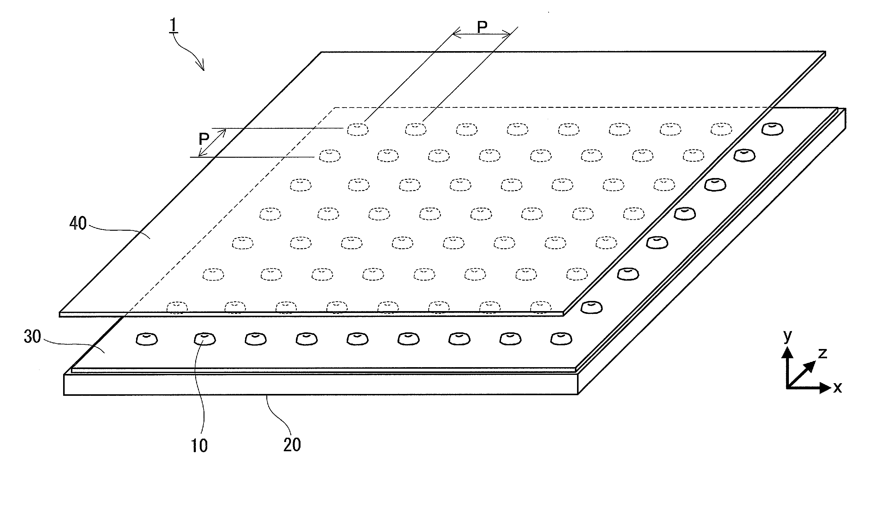
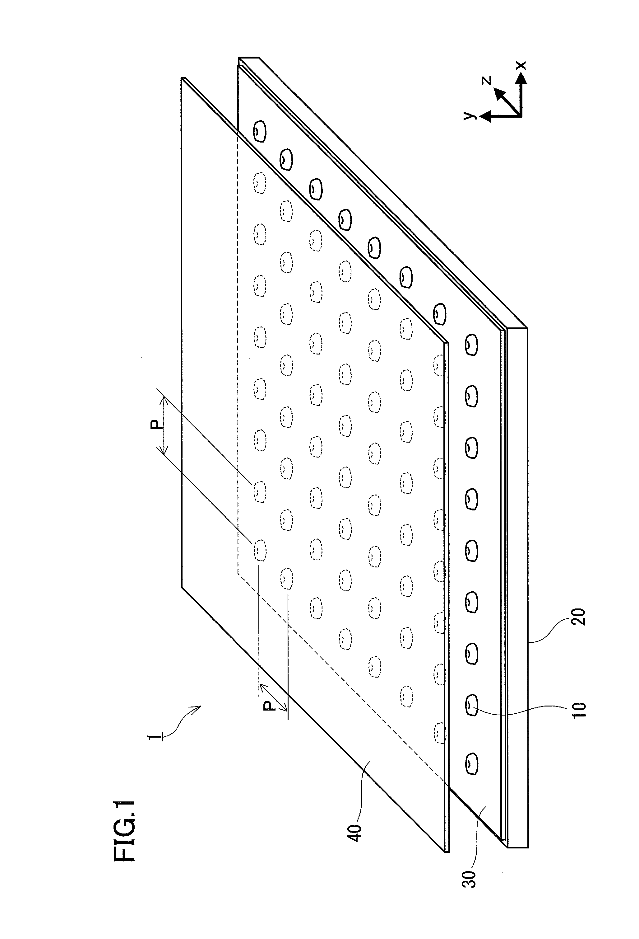
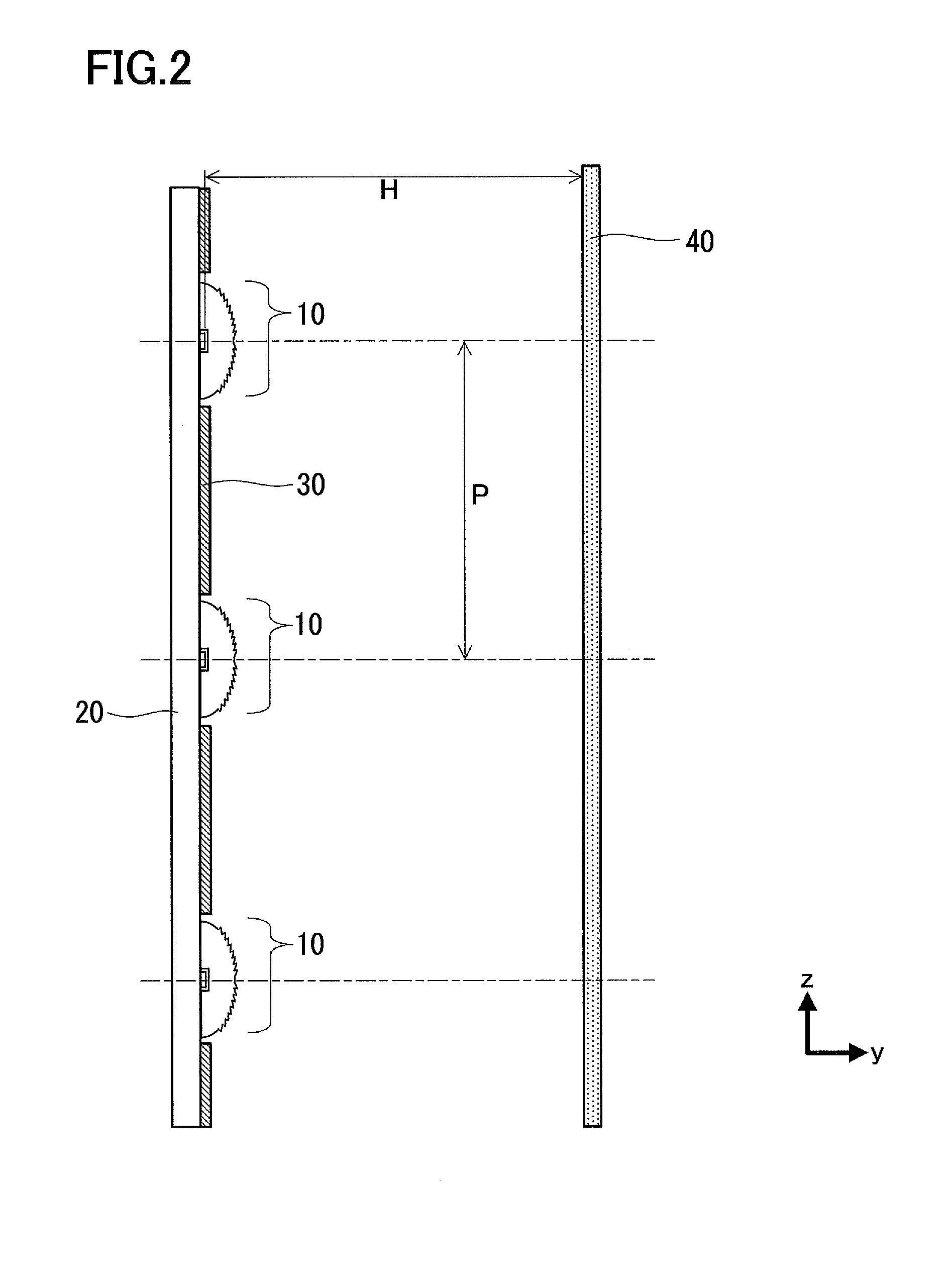
[0050]Hereinafter, an example is given as a specific numerical example of the lens part used in the surface light source 1. In the example, the units of lengths are all millimeters (mm), and the units of angles are all degrees (°) in Tables below. In the surface data in the example, r is a curvature radius, d is a distance between the surfaces or a thickness of the lens part, and n is a refractive index with respect to λ=470 nm. In the example, the surface of the base portion (that is, an interface between the base portion and the diffraction portion) is an aspherical surface, and the shape of the surface is defined by the following equation:

X=Ch21+1-(1+K)C2h2+∑Anhn[Equation1]

where X is the distance from a point on an aspherical surface with a height h from the optical axis to a tangential plane at the vertex of the aspherical surface, h is the height from the optical axis, C is the curvature at the vertex of the aspherical surface (C=1 / R), K is the conical constant, and An is the n...


PUM


Abstract

A lighting device includes a light emitting element that emits a first colored light; a phosphor layer disposed on the light emitting element; and a lens part that is disposed so as to cover the light emitting element and the phosphor layer, and radiates light entering inside of the lens part so as to spread the light radially. The phosphor layer allows a part of the first colored light to transmit therethrough and converts another part of the first colored light into a second colored light having a wavelength longer than that of the first colored light. The lens part has: a base portion forming a light entrance surface through which the first colored light and the second colored light enter the lens part; and a diffraction portion forming a light exit surface through which the first colored light and the second colored light exit the lens part, the diffraction portion being configured so that a refracting power with respect to the second colored light is larger than a refracting power with respect to the first colored light.

Description

BACKGROUND OF THE INVENTION[0001]1. Field of the Invention[0002]The present invention relates to a lighting device used, for example, in a backlight of a liquid-crystal display apparatus, a surface light source including the lighting device, and a liquid-crystal display apparatus including the surface light source.[0003]2. Description of Related Art[0004]In a backlight of a conventional large-sized liquid-crystal display apparatus, a number of cold cathode tubes are disposed right under a liquid crystal panel, and these cold cathode tubes are used together with members such as a diffusing plate and a reflecting plate. In recent years, light emitting diodes (hereinafter referred to as “LEDs”) have been used as light sources for backlights. LEDs have increased their efficiency recently, and are expected to serve as low-power light sources to replace fluorescent lamps. In the case where LEDs are used as a light source in a liquid-crystal display apparatus, the power consumption of the ...

Claims


Application Information

Patent Timeline
IPC IPC(8): G02F1/13357F21V5/00F21V11/00
CPCG02F1/133603G02F1/133606H01L33/58H01L33/50G02F2001/133614G02F1/133614
Inventor MATSUKI, DAIZABUROKIMURA, SYUNSUKEIIYAMA, TOMOKO
Owner PANASONIC CORP
Why Eureka
Try Eureka