Supercharge Your Innovation With Domain-Expert AI Agents!

Light guide panel and apparatus for forming pattern on light guide panel

a technology of light guide panel and pattern, which is applied in the direction of lighting and heating apparatus, printing, instruments, etc., can solve the problems of high defective ratio of removing or smearing parts of printed parts, complex process of manufacturing and printing of ink for forming light guide pattern parts,

Inactive Publication Date: 2011-01-20
HB TECH CO LTD
View PDF2 Cites 9 Cited by
  • Summary
  • Abstract
  • Description
  • Claims
  • Application Information

AI Technical Summary

Benefits of technology

[0024]The apparatus may further include a vacuum unit installed on a lower surface of the light guide panel and preventing the light guide panel from being warped by local heating of the laser beam.

Problems solved by technology

Processes of manufacturing and printing of ink for forming the light guide pattern part 15 are very complicated and a defective ratio of removing or smearing part of a printed portion is very high.
Also, because the light guide panel 11 using the print method cannot be reused after a print pattern is removed, the light guide panel 11 cannot be recycled, thus causing pollution.
Thus, the light guide panel 11 is not environment-friendly.
Particularly, since the light guide pattern part 15 uses optical reflection of a printed ink object itself, the ink object itself unavoidably absorbs light.
This light absorption phenomenon deteriorates the efficiency of light of the surface light source device.
Thus, there is a disadvantage of increasing a cost of development.
As a period of time of manufacturing the metal mold 51 increases, it is difficult for a product model to satisfy a suddenly changing demand for development.
If a product has a thick thickness, a time of cooling after injection increases to several minutes, thus deteriorating productivity.
On the contrary, if a product has a very thin thickness and a wide area, it makes injection imperfect, thus causing a defect such as pattern non-formation.
However, the method has a disadvantage that a process time increases, so productivity decreases because all patterns have to be molded through a laser process one by one at one time.

Method used


Image

  • Light guide panel and apparatus for forming pattern on light guide panel
  • Light guide panel and apparatus for forming pattern on light guide panel
  • Light guide panel and apparatus for forming pattern on light guide panel

Examples


Embodiment Construction

[0050]The following detailed description is provided to assist the reader in gaining a comprehensive understanding of the methods, apparatuses, and / or systems described herein. Accordingly, various changes, modifications, and equivalents of the systems, apparatuses and / or methods described herein will be suggested to those of ordinary skill in the art. The progression of processing steps and / or operations described is an example; however, the sequence of steps and / or operations is not limited to that set forth herein and may be changed as is known in the art, with the exception of steps and / or operations necessarily occurring in a certain order. Also, descriptions of well-known functions and constructions may be omitted for increased clarity and conciseness.

[0051]Hereinafter, the following description is made with reference to the accompanying drawings.

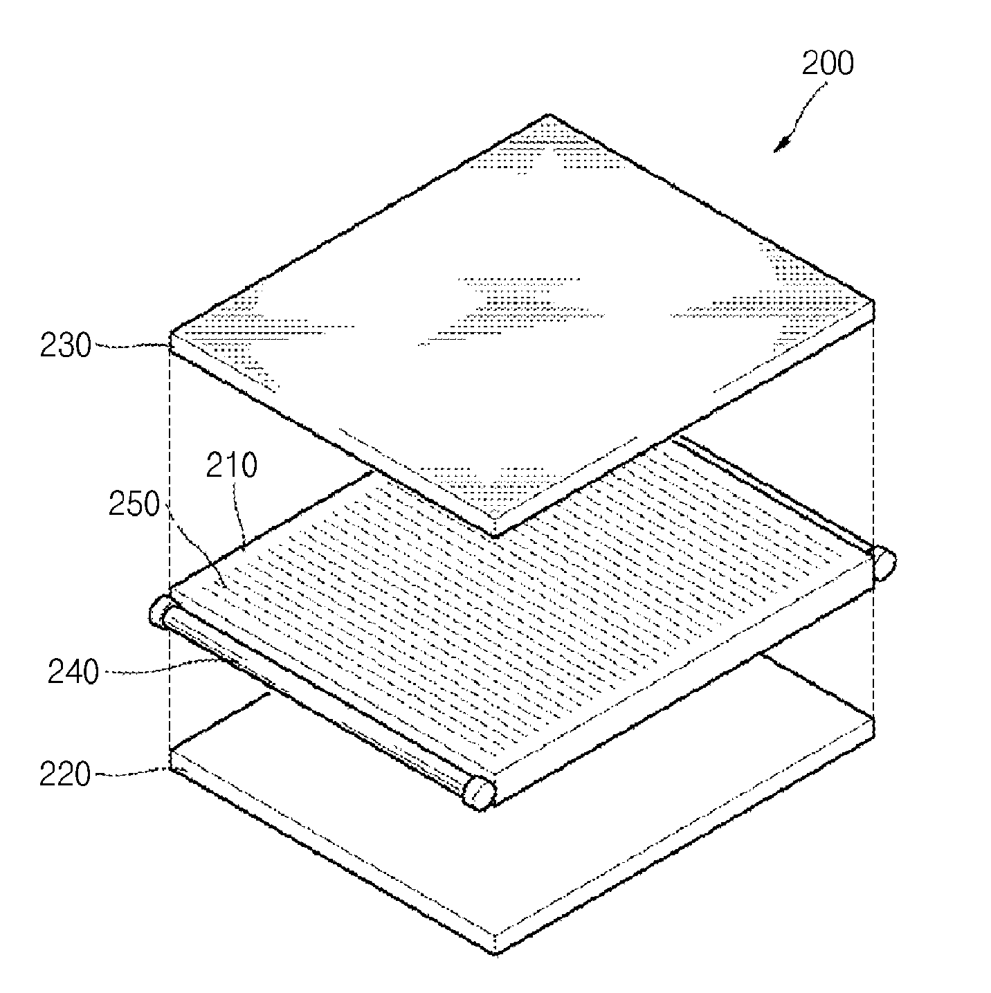
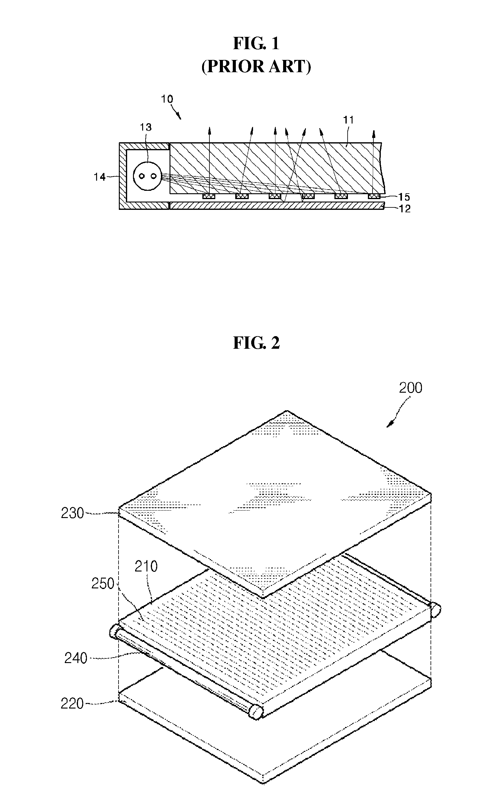
[0052]FIG. 2 is an exploded perspective diagram illustrating a surface light source device applying a light guide panel according to...


PUM


Abstract

A pattern forming apparatus for a light guide panel is provided. The apparatus may include a pattern design system, a control system, a header moving unit including an XY moving unit and a header unit, a laser system, beam splitters, and an optical unit. The pattern design system may have an input of data on a pattern. The control system may connect with the pattern design system and transmits a position signal. The XY moving unit may mechanically move up / down and left / right in response to the position signal. The header unit may be coupled with the XY moving unit and reflects a scanned laser beam. The laser system may output a laser beam by a pulse signal. The beam splitters may split a laser beam into two or more laser beams. The optical unit may reflect and collect the two or more laser beams.

Description

CROSS-REFERENCE TO RELATED APPLICATION(S)[0001]This application is a National Stage entry of International Patent Application No. PCT / KR2008 / 002026, filed on Apr. 10, 2008, the entire disclosure of which is incorporated herein by reference for all purposes.BACKGROUND[0002]1. Field[0003]The following description relates to an apparatus for forming a pattern on a light guide panel that is used for a backlight of a Liquid Crystal Display (LCD), a keypad, a phone, an illuminating surface light source, etc. More particularly, the following description relates to a pattern forming apparatus for forming a light guide pattern by splitting a laser beam into several ones to create a plurality of collected laser beams and scanning the laser beams using a header moving unit movable up / down and left / right, and a light guide panel manufactured using the same.[0004]2. Description of Related Art[0005]In general, a light guide panel is a plate providing a path for uniformly scattering and diffusing ...

Claims


Application Information

Patent Timeline
IPC IPC(8): G03B27/72F21V7/04
CPCG02B6/0036G02F1/1303G02B6/0065G02B6/0061
Inventor PARK, DEUKILRHEW, CHOONGYOPBAEK, KIYONGPARK, DAISOUNG
Owner HB TECH CO LTD
Features
  • R&D
  • Intellectual Property
  • Life Sciences
  • Materials
  • Tech Scout
  • Unparalleled Data Quality
  • Higher Quality Content
  • 60% Fewer Hallucinations
Learn More