X-ray imaging device, method for detecting deviation of flat panel detector, and program for the same

a flat panel detector and imaging surface technology, applied in the field of xray imaging devices, can solve the problems of deviation of the imaging surface of the fpd from the x-ray field, undetectable center of the x-ray field, etc., and achieve the effect of precisely detecting the deviation amoun

Active Publication Date: 2011-01-20
FUJIFILM CORP
View PDF3 Cites 38 Cited by
  • Summary
  • Abstract
  • Description
  • Claims
  • Application Information

AI Technical Summary

Benefits of technology

[0026]According to the present invention, the predetermined patterned images for position detection are formed on the imaging surface of the FPD, and the patterned images of the preliminary radiographic image outputted from the FPD are analyzed to determine the center of the X-ray field. Thus, it is possible to precisely detect a deviation amount, even if the imaging surface of the FPD significantly deviates from the X-ray field so that the center of the X-ray field is out of the imaging surface.

Problems solved by technology

Thus, if a part of the X-ray field lies off the imaging surface due to large deviation, the center of the X-ray field is undetectable.
The reposition of the FPD tends to cause deviation of the imaging surface of the FPD from the X-ray field.

Method used


Image

  • X-ray imaging device, method for detecting deviation of flat panel detector, and program for the same
  • X-ray imaging device, method for detecting deviation of flat panel detector, and program for the same
  • X-ray imaging device, method for detecting deviation of flat panel detector, and program for the same

Examples


first embodiment

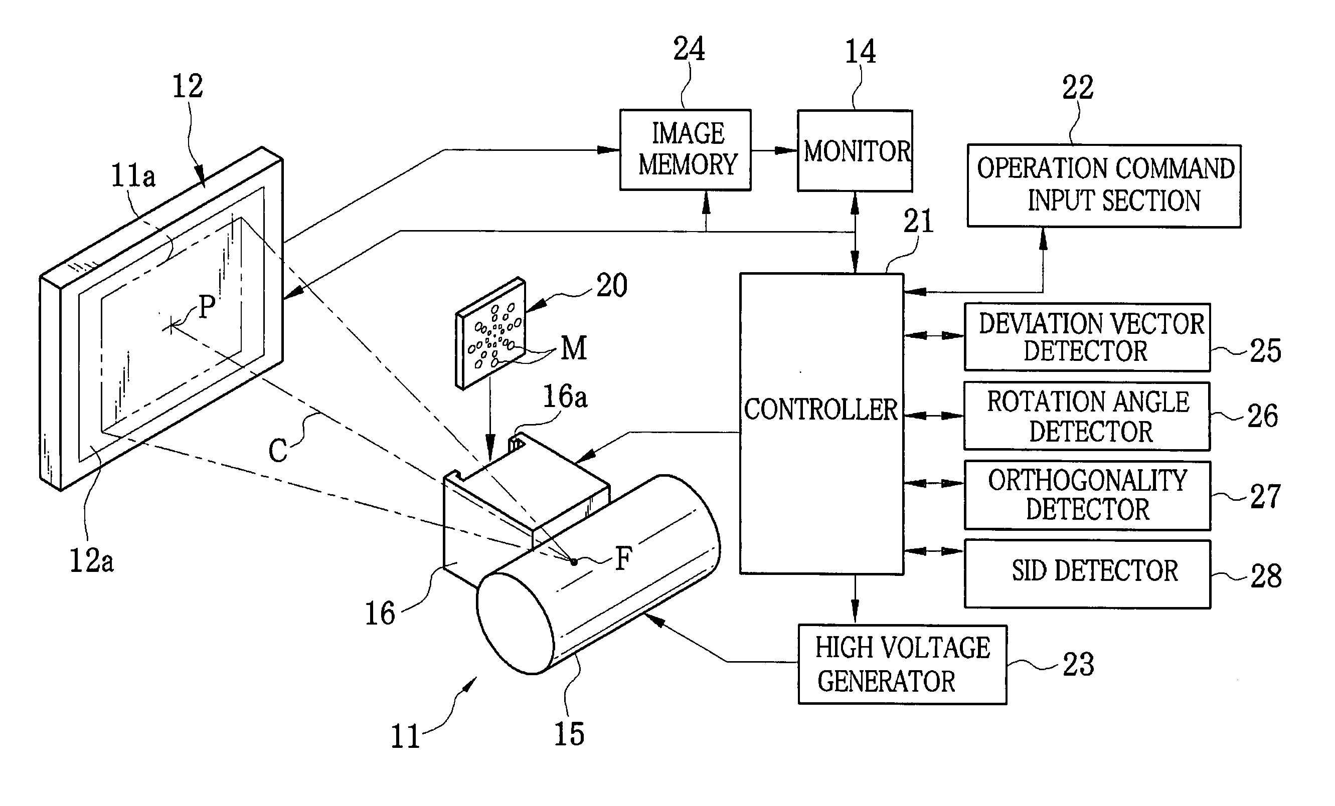
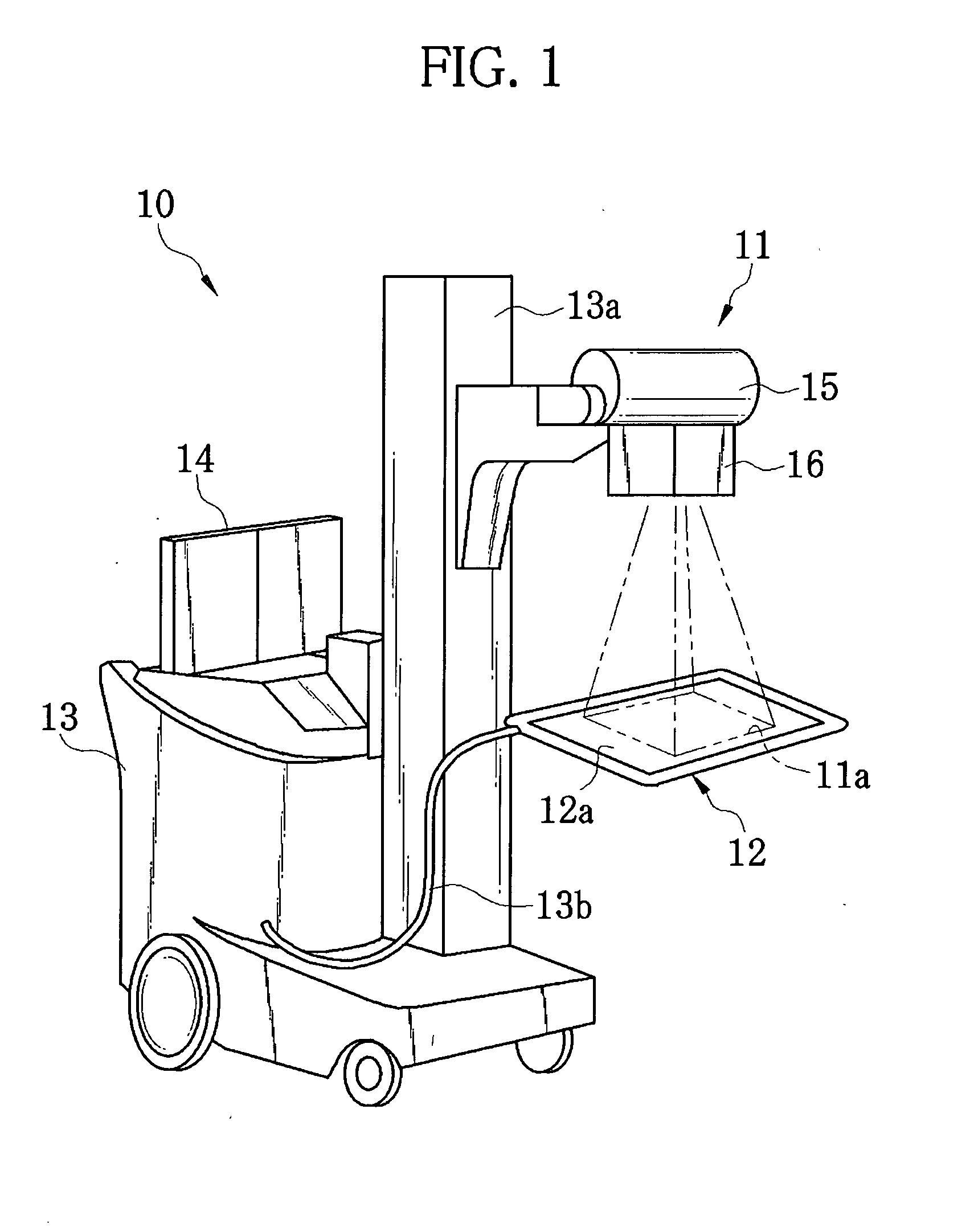
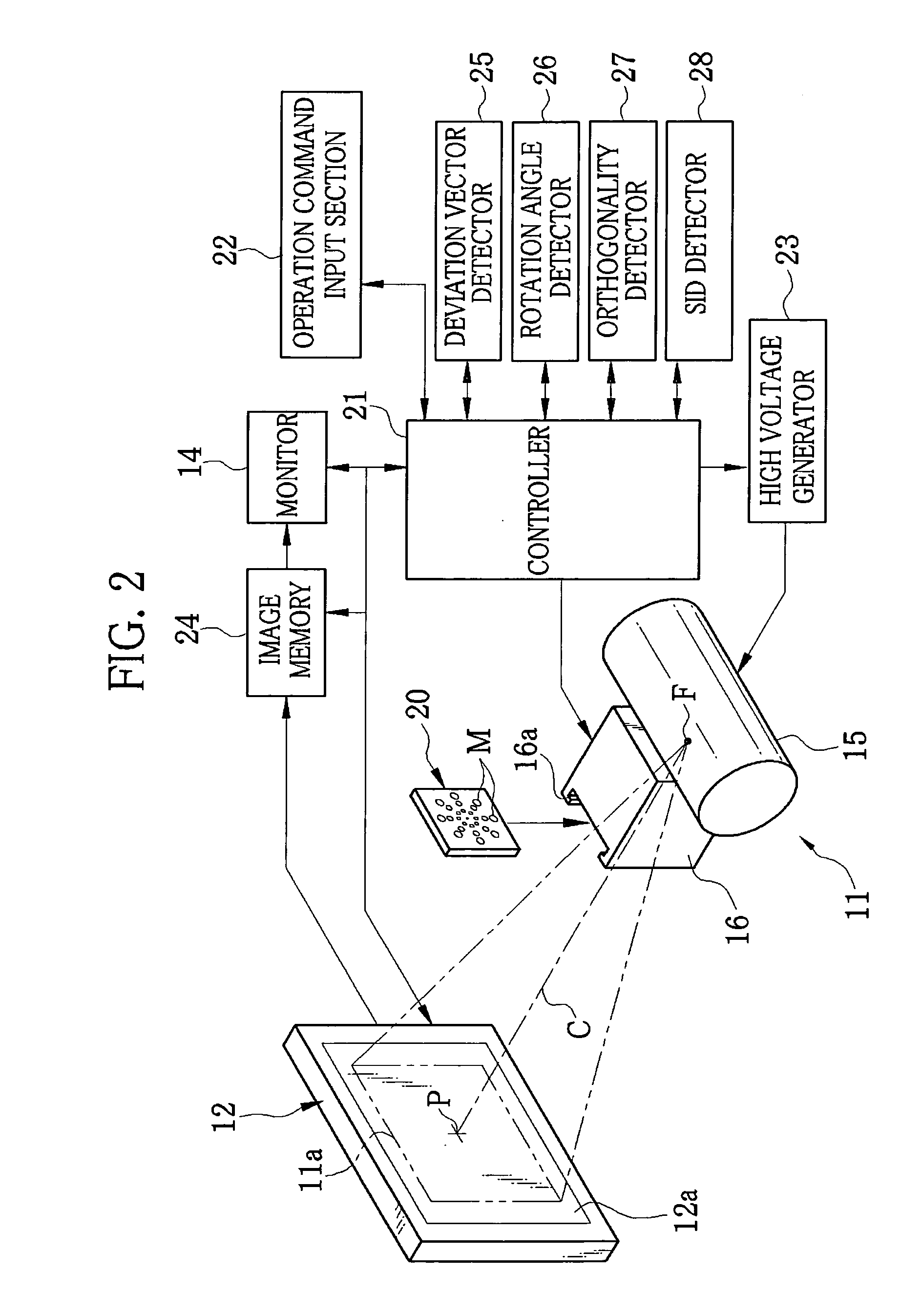
[0043]As shown in FIG. 1, an X-ray imaging device 10 is formed integrally with a cart or a wagon in a movable manner. The X-ray imaging device 10 is constituted of an X-ray generator 11, a portable flat panel detector (FPD) 12 called as an electronic cassette, a main body 13 integrally attached to the cart, and a monitor 14 attached to the main body 13. The X-ray generator 11 is slidably attached to a column 13a, and emits an X-ray radiation beam as shown by chain double-dashed lines of FIG. 1. The emitted X-ray radiation beam passes through patient's body, and then the FPD 12 receives the X-ray radiation beam to produce a radiographic image. The FPD 12 is connected to the main body 13 through a cable 13b.

[0044]On the monitor 14, which is a liquid crystal display, the radiographic image outputted from the FPD 12, a GUI (graphical user interface) image, and the like are displayed.

[0045]The main body 13 contains a controller 21 (see FIG. 2). The controller 21 controls the operation o...

second embodiment

[0085]In an X-ray imaging device according to a second embodiment, the markers M0 to M3 are formed in the collimator leaves, in order to produce the preliminary radiographic image without using the filter plate 20 or 30. The X-ray imaging device according to the second embodiment has the same structure as that of the X-ray imaging device 10 according to the first embodiment, except for the collimator leaves.

[0086]As shown in FIG. 13, a collimator unit 40 according to the second embodiment is provided with first and second collimator leaves 41a and 41b that are openable and closable in the X direction, and third and fourth collimator leaves 41c and 41d that are openable and closable in the Y direction. In the first and second collimator leaves 41a and 41b, circular holes are formed as the markers M0 to M3. By closing the first and second collimator leaves 41a and 41b, the markers M0 to M3, which are in the same layout as those of the filter plate 20 shown in FIG. 3, appear in the fir...

third embodiment

[0090]In the X-ray imaging devices according to the first and second embodiments, the holes of the markers M0 and M3 are formed in the filter plate or the collimator leaves, and the preliminary radiographic image is produced from the X-ray radiation beam that has passed through the markers M0 to M3. In contrast, an X-ray imaging device according to a third embodiment produces the preliminary radiographic image in which X-ray density is reduced in stages from center to edge, with use of a filter plate that has different X-ray transmittance from area to area.

[0091]In FIG. 14, a filter plate 50 of the third embodiment is divided into first to fourth areas 50a to 50d that have different X-ray transmittance. The square first area 50a disposed at the center of the filter plate 50 has transmittance of approximately 90%. The square frame-shaped second area 50b surrounding the first area 50a has transmittance of approximately 70%. The square frame-shaped third area 50c surrounding the second...


PUM


Abstract

An X-ray imaging device includes an X-ray generator, a filter plate detachably attached to an X-ray outlet of the X-ray generator, and a FPD. The filter plate has a plurality of circular markers of different sizes. The smallest marker is disposed at the center of the filter plate. The other markers are disposed on lines radiating from the smallest marker in increasing order of size and at regular intervals. An X-ray radiation beam passes through the markers and patient's body, and is incident upon an imaging surface of the FPD. The FPD produces a preliminary radiographic image from the incident X-ray radiation beam. A deviation vector detector chooses adjoining two marker images of different sizes from the preliminary radiographic image, and identifies to which markers the marker images correspond based on a size ratio. Then, the deviation vector detector determines the center of an X-ray field.

Description

BACKGROUND OF THE INVENTION[0001]1. Field of the Invention[0002]The present invention relates to an X-ray imaging device using a flat panel detector (FPD), a method, and a program for detecting deviation between the FPD and an X-ray field.[0003]2. Description Related to the Prior Art[0004]Digital radiography using a flat panel detector (FPD) for X-ray imaging has come into widespread use in a medical field in recent years. The FPD has small size, light weight, and a large imaging surface. In an X-ray imaging device having the FPD, an X-ray radiation beam produced by an X-ray generator is applied to patient's body part to be viewed. The X-ray radiation beam passes through the body part of the patient, and the FPD captures the X-ray radiation beam behind the body part. The FPD produces a digital-format radiographic image from the captured X-ray radiation beam. The FPD can immediately apply image processing or enhancement to the radiographic image because the radiographic image is in t...

Claims


Application Information

Patent Timeline
Patent Type & Authority Applications(United States)
IPC IPC(8): A61B6/08
CPCA61B6/583A61B6/588A61B6/587
Inventor TAKAHASHI, SHOJI
Owner FUJIFILM CORP
Why Eureka
Try Eureka