Core assembly for winding sheet and winding method

a technology of core assembly and winding method, which is applied in the direction of transportation and packaging, thin material processing, filament handling, etc., can solve the problems of high structural cost, difficult adjustment of outer diameter of the core assembly, and failure to keep high precision of the inner diameter of the sheet roll

Inactive Publication Date: 2011-01-27
FUJIFILM CORP
View PDF0 Cites 16 Cited by
  • Summary
  • Abstract
  • Description
  • Claims
  • Application Information

AI Technical Summary

Benefits of technology

[0017]The regulating device further positions the shaft hub in the first position in the axial direction, to maintain a small diameter for the outer diameter.

Problems solved by technology

As the sheet roll is shipped commercially in a form wound about the internal support core, the internal support core will be a waste produced to discard after use of the sheet roll.
However, the method of JP-A 6-127758 has a problem in that a specific pump is required for blow and discharge of air, and will raise the structural cost.
Furthermore, adjustment of the outer diameter of the core assembly is difficult because of easy compression of air.
There is a drawback of failure in keeping high precision of an inner diameter of the sheet roll due to a change in the outer diameter of the core assembly in the course of winding the continuous sheet.
This problem is typically serious in a surface winding method in which torque is applied to a peripheral surface of the core assembly for rotating the same.

Method used


Image

  • Core assembly for winding sheet and winding method
  • Core assembly for winding sheet and winding method
  • Core assembly for winding sheet and winding method

Examples


Embodiment Construction

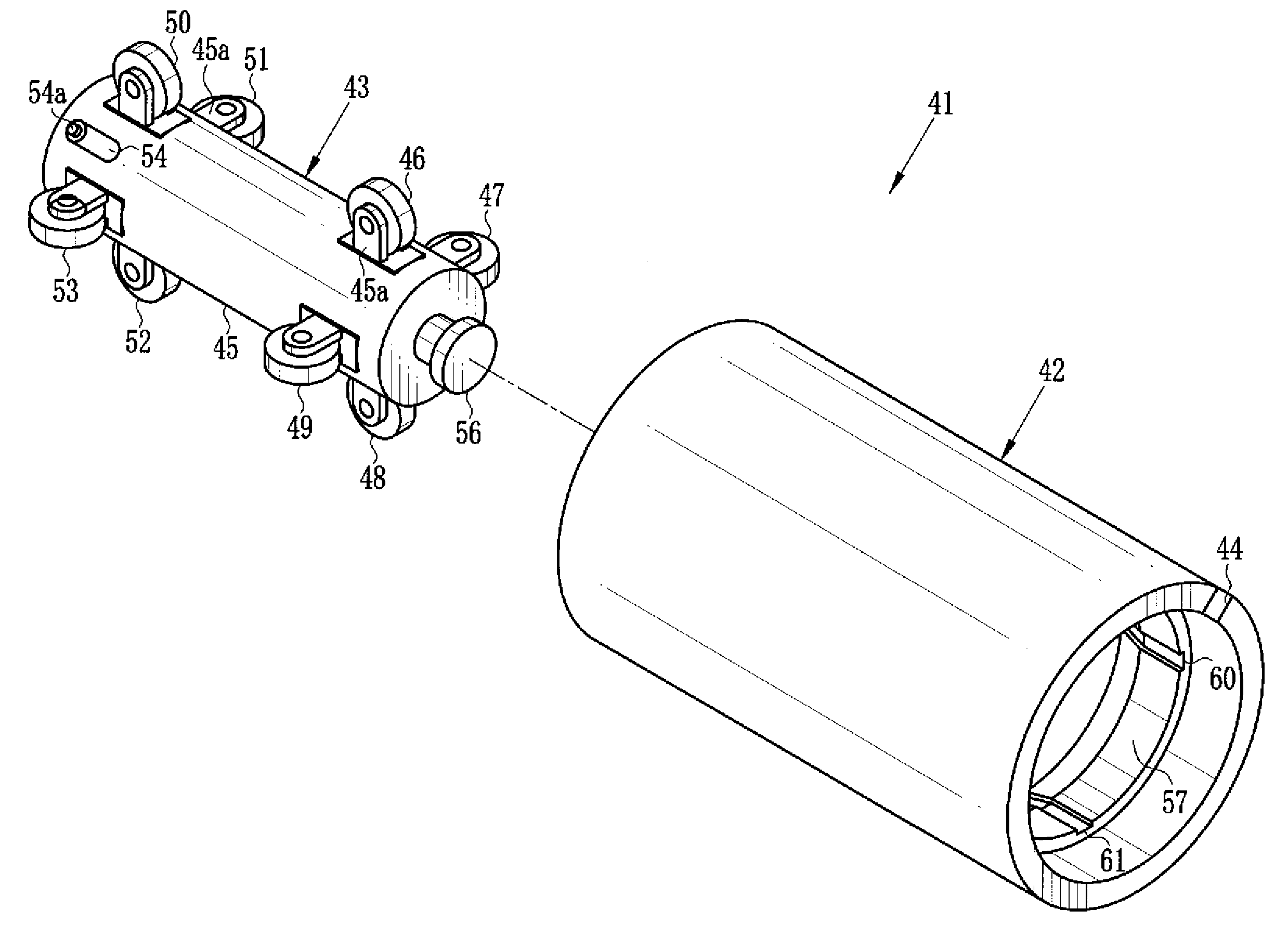
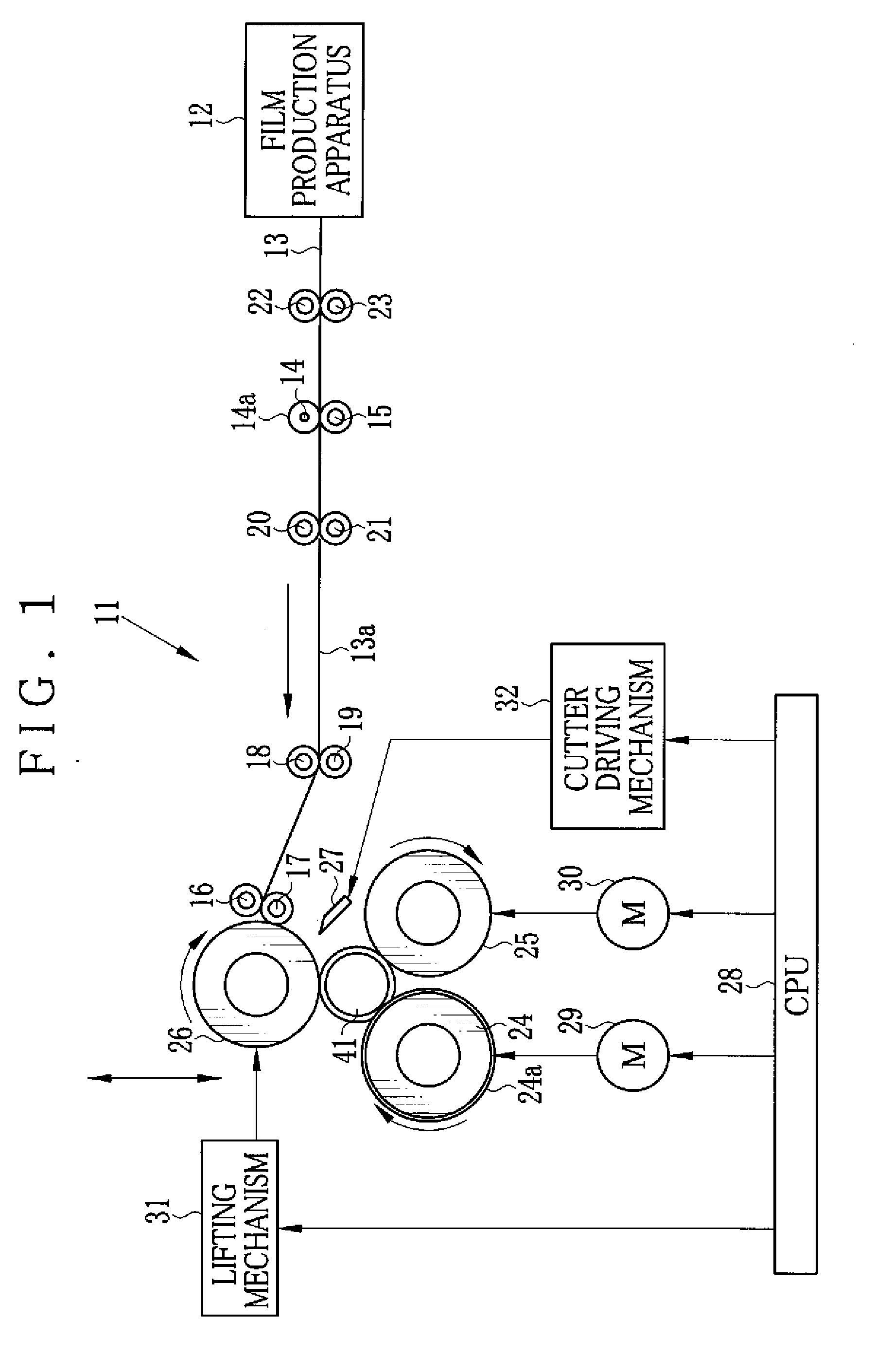
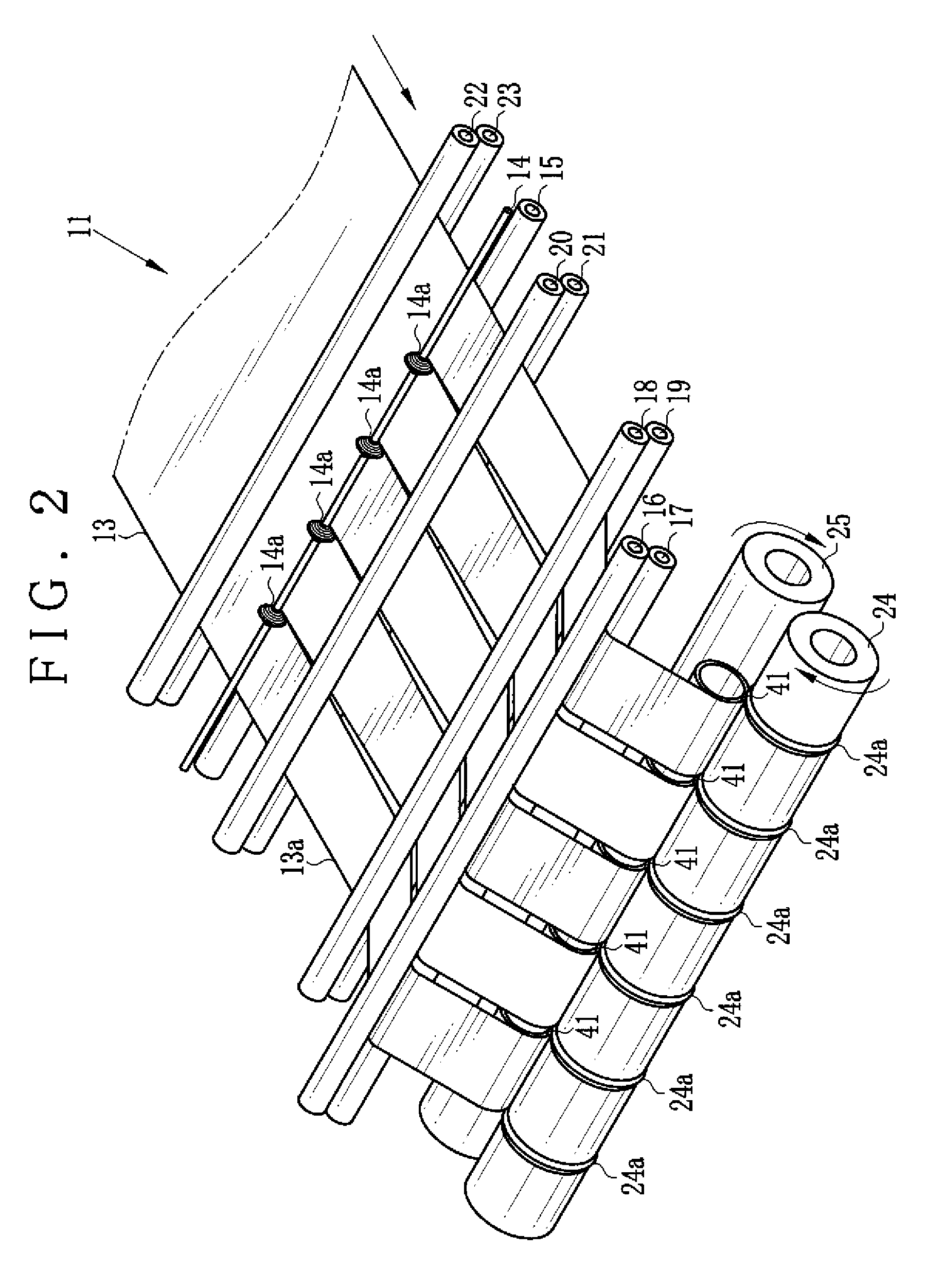
[0043]In FIGS. 1 and 2, a film winding system 11 or a film winding line is connected with a film production apparatus 12. Film web 13 is produced by the film production apparatus 12 continuously. A plurality of continuous sheets 13a or continuous film of a strip shape are formed by slitting the film web 13. In the film winding system 11, a core assembly 41 or spool assembly or a winder winds the continuous sheet 13a to obtain a sheet roll 71 or film roll. See FIG. 8.

[0044]The film winding system 11 includes a slitting roller 14, a blade receiving roller 15, guide rollers 16, 17, 18, 19, 20, 21, 22 and 23, surface rollers 24 and 25, a rider roller 26, a cutter 27, a CPU 28, motors 29 and 30, a lifting mechanism 31 and a cutter driving mechanism 32. In FIG. 2, elements are clarified in a simplified manner, so the rider roller 26, the cutter 27, the CPU 28, the motors 29 and 30, the lifting mechanism 31 and the cutter driving mechanism 32 are not illustrated.

[0045]A plurality of blades...


PUM

PropertyMeasurementUnit
shapeaaaaaaaaaa
outer diameteraaaaaaaaaa
pressureaaaaaaaaaa

Abstract

A core assembly for a continuous sheet includes a core of a cylindrical form. A side channel is formed in the core to extend fully in an axial direction thereof. A shaft hub is disposed through the core movably in the axial direction. A changing unit or adjuster displaces the core in response to moving of the shaft hub between first and second positions, and enlarges an outer diameter of the core when the shaft hub is in the second position than when the shaft hub is in the first position. Preferably, the changing unit includes a cam roller, disposed on the shaft hub, for projecting in a radial direction. A cam ramp surface is formed with an inner surface of the core, has a height increasing toward the second position, is pressed by the cam roller.

Description

BACKGROUND OF THE INVENTION[0001]1. Field of the Invention[0002]The present invention relates to a core assembly for winding a sheet and a winding method. More particularly, the present invention relates to a core assembly for winding a sheet to form a sheet roll without an internal support core in an efficient manner, and a winding method.[0003]2. Description Related to the Prior Art[0004]A continuous sheet or continuous film is a material of plastic film, paper or the like and is manufactured continuously. A sheet roll or film roll of the continuous sheet is provided in a form wound about an internal support core. As the sheet roll is shipped commercially in a form wound about the internal support core, the internal support core will be a waste produced to discard after use of the sheet roll.[0005]Various methods of producing the sheet roll without the internal support core has been suggested. JP-A 6-127758 discloses the use of a core assembly or spool assembly in which air is blo...

Claims


Application Information

Patent Timeline
Patent Type & Authority Applications(United States)
IPC IPC(8): B65H75/24B65H75/10B65H19/30B65H19/22
CPCB65H75/10B65H2301/41828B65H75/22
Inventor NAKANISHI, TAISUKEKUMAGAYA, MASATOSHI
Owner FUJIFILM CORP
Why Eureka
Try Eureka