Noncontact power feed system, noncontact relay apparatus, noncontact power reception apparatus, and noncontact power feed method

Active Publication Date: 2011-01-27
SONY CORP
View PDF2 Cites 43 Cited by
  • Summary
  • Abstract
  • Description
  • Claims
  • Application Information

AI Technical Summary

Benefits of technology

[0034]Specifically, through the mediation of a moving noncontact power reception/relay apparatus, it is possible to provide a new power-supply mode that uses a power supply technique of a so-called resonance type such as a magnetic field resonance type and a n

Problems solved by technology

However, a shorter distance between the resonance devices does not increase the coupling mount, and a distance at which the coupling mount becomes a maxi

Method used


Image

  • Noncontact power feed system, noncontact relay apparatus, noncontact power reception apparatus, and noncontact power feed method
  • Noncontact power feed system, noncontact relay apparatus, noncontact power reception apparatus, and noncontact power feed method
  • Noncontact power feed system, noncontact relay apparatus, noncontact power reception apparatus, and noncontact power feed method

Examples


Example

First Embodiment

Outline of Noncontact Power Feed System of First Embodiment

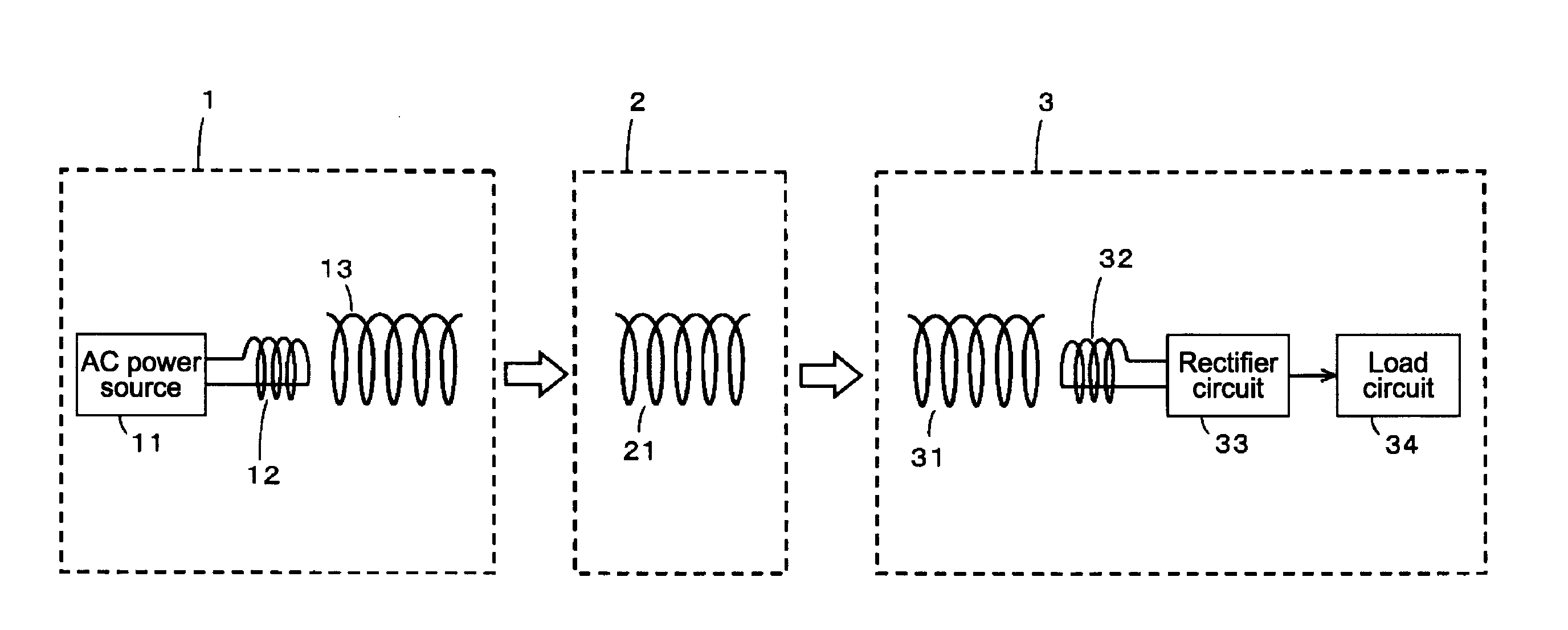
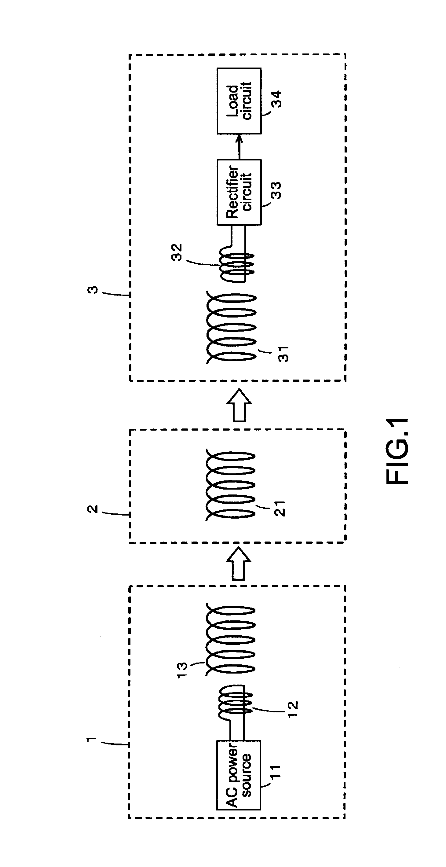
[0052]FIG. 1 is a diagram for explaining a structural example of a magnetic-field-resonance-type noncontact power feed system according to a first embodiment of the present invention. As shown in FIG. 1, the noncontact power feed system of this embodiment includes a power feed source 1, a moving body 2, and a power feed destination 3. It should be noted that a plurality of power feed destinations that are similarly structured can be used, which will be described later in detail.

[0053]The power feed source 1 uses a magnetic field resonance system to supply power to another electronic apparatus in a noncontact manner, thus realizing a function as a noncontact power feed apparatus.

[0054]The moving body 2 receives power from the power feed source 1 and has a function as a relay apparatus that supplies the power to another electronic apparatus and a function of using the power to drive a drive motor thereof, thus ...

Example

Second Embodiment

Outline of Noncontact Power Feed System of Second Embodiment

[0115]The noncontact power feed system according to the first embodiment described above has a relatively small size such that the noncontact power feed system can be provided on a table, for example. On the other hand, a noncontact power feed system according to a second embodiment is formed as one of amusement attractions in a theme park, in which a moving body can be moved while taking humans thereon.

[0116]FIG. 5 is a diagram for explaining the noncontact power feed system according to the second embodiment. As shown in FIG. 5, the noncontact power feed system according to the second embodiment includes a plurality of power feed sources 1(1), 1(2), 1(3), . . . , a moving body 2A having a structure of an automobile, and a plurality of power feed destinations 3(1), 3(2), 3(3), . . . .

[0117]Each of the plurality of power feed sources 1(1), 1(2), 1(3), . . . realizes a function as a noncontact power feed app...


PUM


Abstract

A noncontact power feed system includes: a noncontact power feed apparatus including a power feed resonance device to supply alternate-current power to an electronic apparatus by resonance in a noncontact manner, and an alternate-current power source section to generate the alternate-current power and supply it to the power feed resonance device; a noncontact relay apparatus including a relay resonance device to receive the alternate-current power and relay it to another electronic apparatus by resonance in a noncontact manner, a relay-side rectifier circuit to form direct-current power for output, and a movement means for moving the noncontact relay apparatus by the direct-current power; and at least one noncontact power reception apparatus including a power reception resonance device to receive the alternate-current power by magnetic field resonance in a noncontact manner, a power-reception-side rectifier circuit to form direct-current power for output, and a load means driven by the direct-current power.

Description

BACKGROUND OF THE INVENTION[0001]1. Field of the Invention[0002]The present invention relates to a noncontact power feed system that feeds power by using resonance phenomena such as magnetic field resonance and electric field rescnance, an apparatus used in the system, and a noncontact power feed method used for the system and the apparatus.[0003]2. Description of the Related Art[0004]As techniques of enabling electric energy to be transmitted in a noncontact manner, there are an electromagnetic induction system and a magnetic field resonance system. The electromagnetic induction system and the magnetic field resonance system are different from each other in various points as described below, and in recent years, an energy transmission using the magnetic field resonance system has attracted attention.[0005]FIG. 11 is a block diagram showing a structural example of a magnetic-field-resonance-type noncontact power feed system in which a power feed source and a power feed destination h...

Claims


Application Information

Patent Timeline
IPC IPC(8): H02J17/00B60L5/00B60M7/00G09F13/00G09F21/04H01F38/18
CPCB60L11/182H02J5/005Y02T90/14Y02T10/7005Y02T90/122H02J17/00Y02T10/7072H02J50/12B60L53/122B60L53/126Y02T10/70H02J50/50H02J50/80H02J50/40Y02T90/12
Inventor WADA, HIROTSUGUFUJIMAKI, KENICHI
Owner SONY CORP
Why Eureka
Try Eureka