Piezoelectric vibrator, manufacturing method of piezoelectric vibrator, oscillator, electronic device, and radio-controlled clock

Inactive Publication Date: 2011-01-27
SEIKO INSTR INC
View PDF12 Cites 12 Cited by
  • Summary
  • Abstract
  • Description
  • Claims
  • Application Information

AI Technical Summary

Benefits of technology

[0033]In the piezoelectric vibrator according to the above aspect of the present invention, since the degree of vacuum in the cavity can be secured, it is possible to decrease the series resonance resistance value to a suitable value and to thus suppress production of defective products to increase the yield. Therefore, it is possible to reduce the cost of an oscillator, an electronic device, and a radio-controlled clock.
[0034]According to the piezoelectri

Problems solved by technology

However, in the piezoelectric vibrator of the related art, there is a case where the degree of vacuum in the cavity cannot be increased to satisfy a predetermined requirement even when the entire areas of the gettering material are gettered.
A piezoelec

Method used


Image

  • Piezoelectric vibrator, manufacturing method of piezoelectric vibrator, oscillator, electronic device, and radio-controlled clock
  • Piezoelectric vibrator, manufacturing method of piezoelectric vibrator, oscillator, electronic device, and radio-controlled clock
  • Piezoelectric vibrator, manufacturing method of piezoelectric vibrator, oscillator, electronic device, and radio-controlled clock

Examples


first embodiment

[0054]Hereinafter, a piezoelectric vibrator according to a first embodiment of the present invention will be described with reference to the drawings.

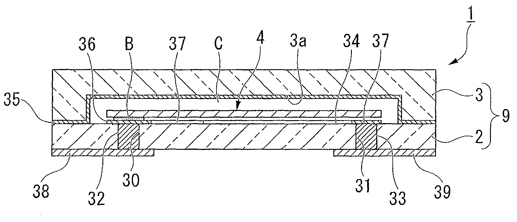
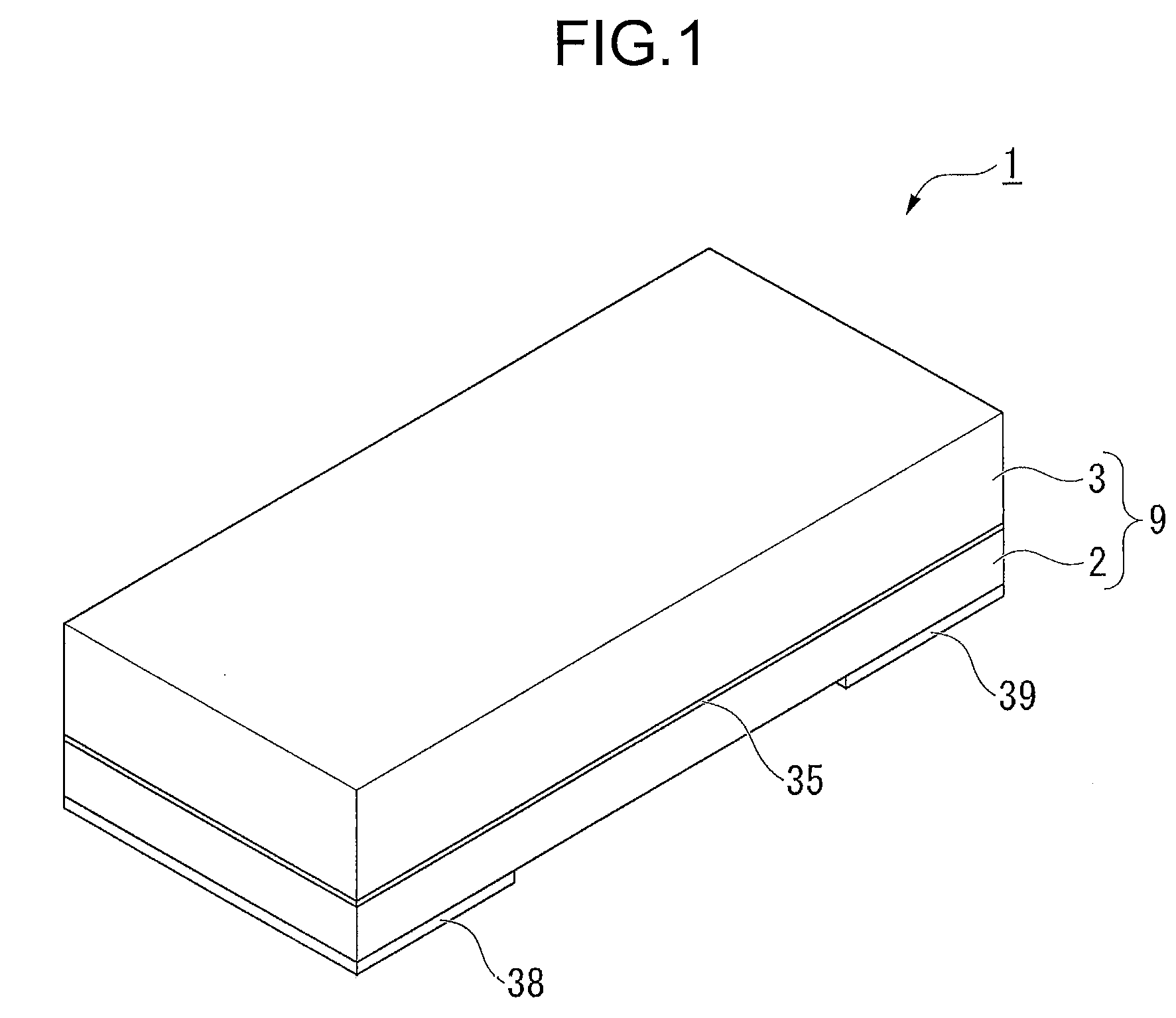
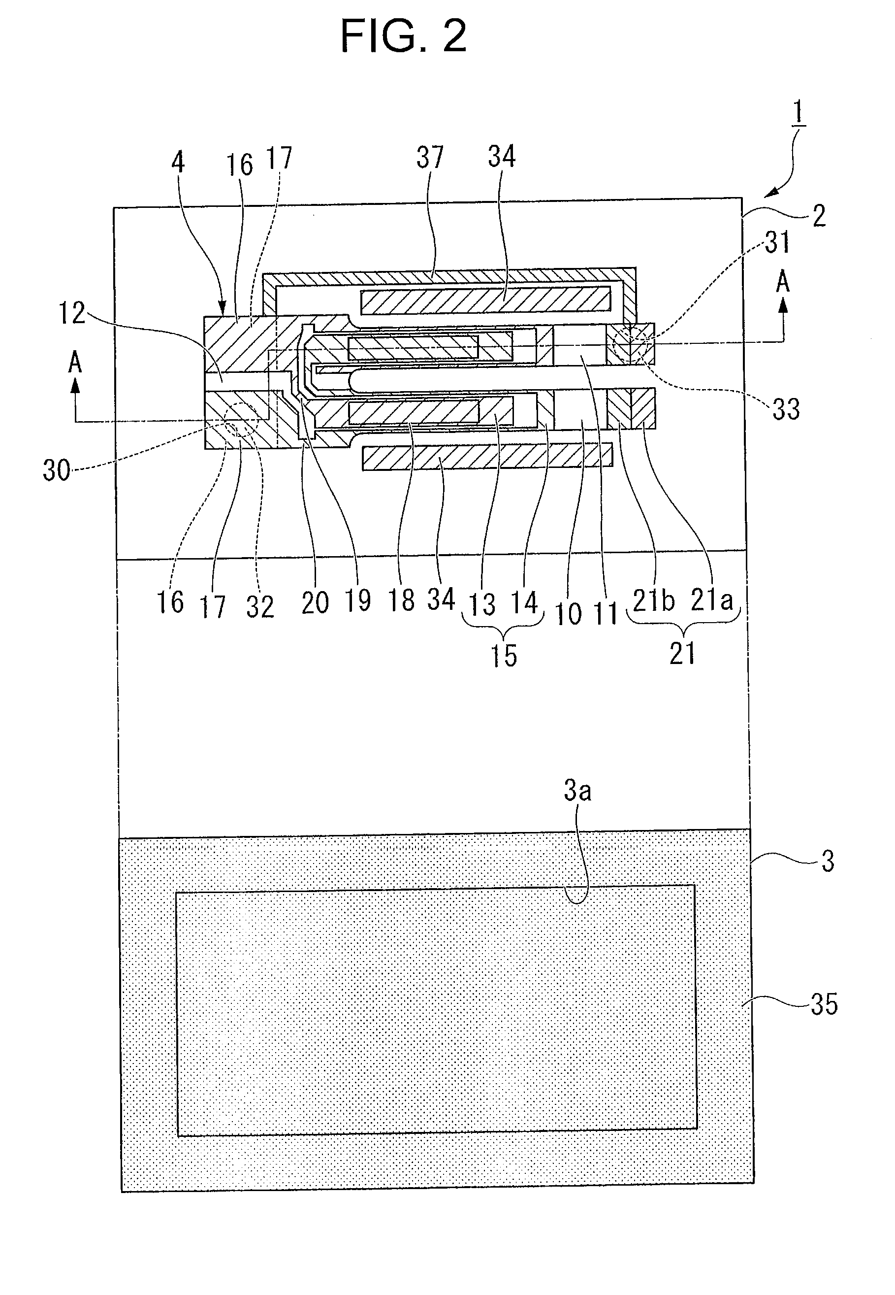
[0055]As shown in FIGS. 1 to 4, a piezoelectric vibrator 1 according to the present embodiment is a SMD-type piezoelectric vibrator including: a base board 2 and a lid board 3 which are superimposed onto each other to form a cavity C therebetween; and a piezoelectric vibrating reed 4 which is accommodated in the cavity C and bonded to the base board 2, and is a work in process in the progress of manufacturing a piezoelectric vibrator 70 described later which is a finished product.

[0056]In FIGS. 3 and 4, for better understanding of the drawings, illustrations of piezoelectric vibrating reed 4, excitation electrode 15, extraction electrodes 19 and 20, mount electrodes 16 and 17, and weight metal film 21 are omitted.

Piezoelectric Vibrating Reed

[0057]As shown in FIGS. 5 to 7, the piezoelectric vibrating reed 4 is a turning-fork type vibrat...

second embodiment

[0103]Next, a piezoelectric vibrator according to a second embodiment of the present invention will be described with reference to FIG. 11.

[0104]In the second embodiment, the same constituent elements as those in the first embodiment will be denoted by the same reference numerals, and description thereof will be omitted and only the points of difference will be described.

[0105]In a piezoelectric vibrator 80 of the present embodiment, second laser irradiation marks 81 are formed at portions of the bonding film 35 in the cavity C where they do not overlap with the gettering material 34 as viewed from the normal direction of the base board 2.

[0106]In the example shown in the drawing, the second laser irradiation marks 81 are formed to be adjacent or continuous to a part of the first laser irradiation marks 71. Moreover, the second laser irradiation marks 81 are formed at positions where they do not overlap with the piezoelectric vibrating reed 4, the penetration electrodes 32 and 33, t...


PUM

PropertyMeasurementUnit
Electrical resistanceaaaaaaaaaa
Areaaaaaaaaaaa
Efficiencyaaaaaaaaaa

Abstract

Providing a piezoelectric vibrator which is capable of securing the degree of vacuum in a cavity and can be manufactured with high efficiency and to provide a manufacturing method thereof. A piezoelectric vibrator 1 including: a base board 2 and a lid board 3 which are superimposed onto each other so as to form a cavity C therebetween; a piezoelectric vibrating reed 4 which is accommodated in the cavity and bonded to the base board; a gettering material 34 which is formed in the base board to be accommodated in the cavity; a bonding film 35 which is formed on the entire surface of the lid board facing the base board so as to bond both boards to each other at a portion thereof being in contact with the base board, wherein the bonding film is formed of a material which is capable of absorbing surrounding gas by being activated with laser irradiation.

Description

RELATED APPLICATIONS[0001]This application claims priority under 35 U.S.C. §119 to Japanese Patent Application No. 2009-173382 filed on Jul. 24, 2009, the entire content of which is hereby incorporated by reference.BACKGROUND OF THE INVENTION[0002]1. Field of the Invention[0003]The present invention relates to an SMD-type piezoelectric vibrator in which a piezoelectric vibrating reed is sealed in a cavity formed between two bonded boards, a manufacturing method of the piezoelectric vibrator, and an oscillator, an electronic device, and a radio-controlled clock each having the piezoelectric vibrator.[0004]2. Description of the Related Art[0005]Recently, a piezoelectric vibrator using a piezoelectric vibrating reed made of a piezoelectric material such as quartz crystal is used in a cellular phone and a portable information terminal as the time source, the timing source of a control signal, a reference signal source, and the like. As the piezoelectric vibrating reed, a turning-fork ty...

Claims


Application Information

Patent Timeline
IPC IPC(8): H01L41/053H01L41/22H01L23/02H01L23/26H03H3/04H03H9/02
CPCH03H3/04H03H9/02149H03H9/1021H03H9/21Y10T29/42H03H2003/0478H03H2003/0492H03H2009/02165G04R20/10H03H2003/026
Inventor FUKUDA, JUNYA
Owner SEIKO INSTR INC
Why Eureka
Try Eureka