Medical image display device and medical image display method

a medical image and display device technology, applied in the field of medical image display devices and medical image display methods, can solve problems such as artifact generation on deployment images, and achieve the effect of preventing artifact generation and high-quality images

Active Publication Date: 2011-01-27
FUJIFILM HEALTHCARE CORP
View PDF6 Cites 36 Cited by
  • Summary
  • Abstract
  • Description
  • Claims
  • Application Information

AI Technical Summary

Benefits of technology

[0032](4) a step that changes the direction in which the cross-section is to be set according to bending curvature of the hollow organ so as to prevent generation of artifacts.
[0033]In accordance with the present in

Problems solved by technology

However, the following problems still remains in the above-mentioned conventional techniques.
In those cases, along with progress of the respective set positions in the hollow organ on the center line, the

Method used


Image

  • Medical image display device and medical image display method
  • Medical image display device and medical image display method
  • Medical image display device and medical image display method

Examples


embodiment 1

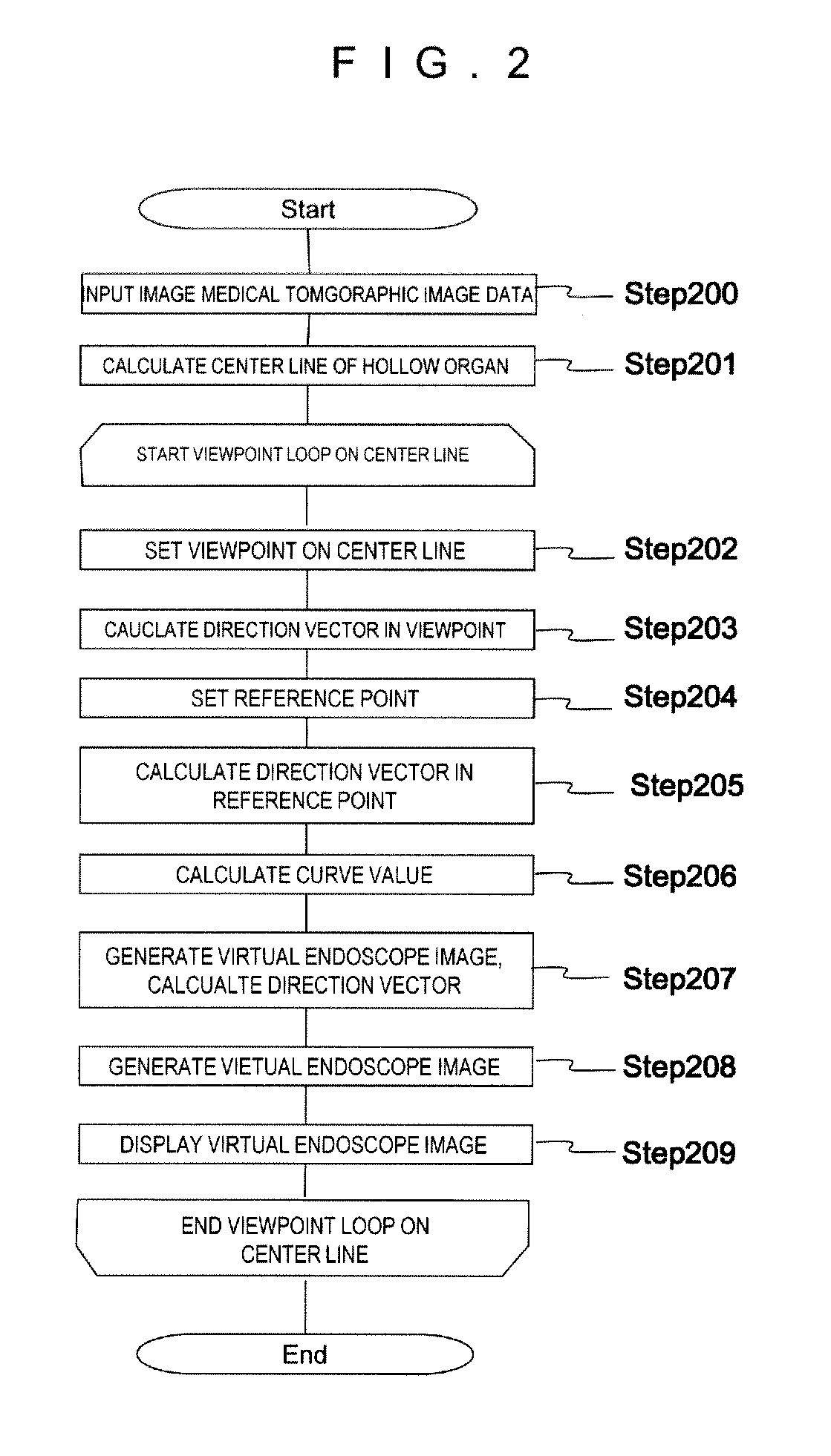
[0062]First embodiment of the present invention will be described using FIG. 1˜FIG. 5. FIG. 2 shows the flowchart thereof. Embodiment 1 will be described according to the flowchart.

[0063](Step 200)

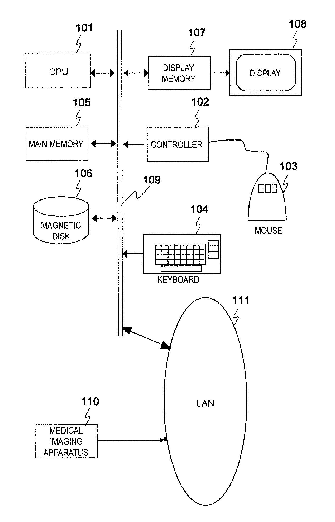
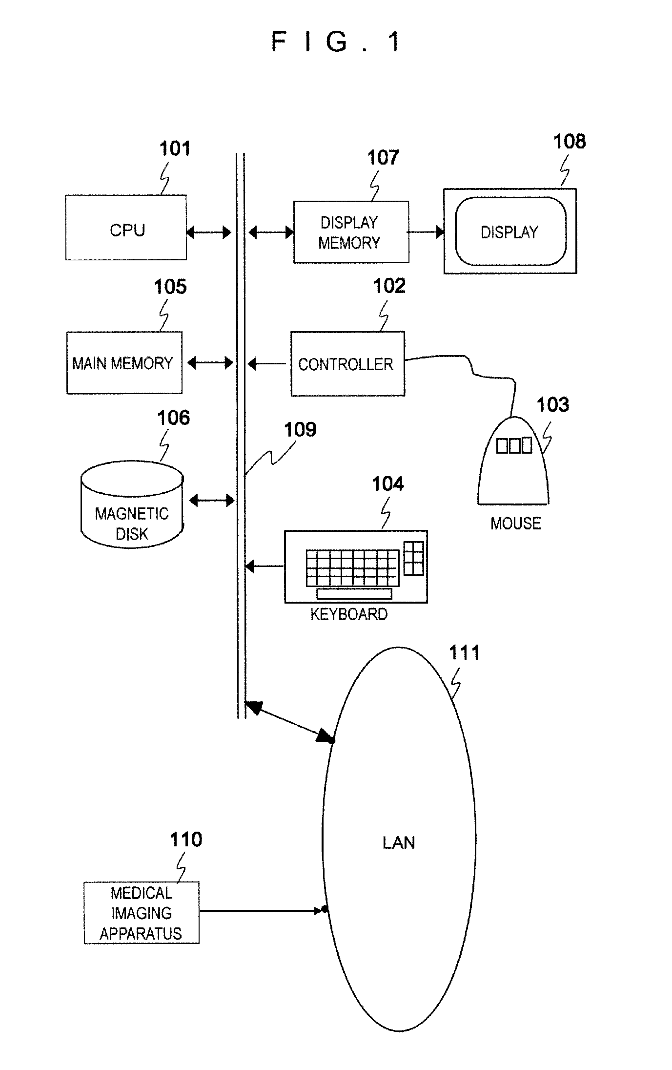
[0064]An operator executes predetermined operations using an input device such as mouse 103 or keyboard 104, and inputs a medical tomographic image taken by medical image diagnostic apparatus 110, for example, a multi-slice image taken by an X-ray CT apparatus to main memory 105. In other words, the main memory is, in the present embodiment, used as storage means for storing the slice images of the object obtained by a medical image diagnostic apparatus.

[0065](Step 201)

[0066]CPU 101 extracts the center line of a hollow organ to be the observation target using the hollow organ center line extraction method disclosed in, for example, JP-A-2006-42969 from the medical tomographic image inputted in step 200. More concretely, in paragraph number 0016 (step 63) of JP-A-2006-42969, the method is d...

embodiment 2

[0091]Embodiment 2 in the present invention will be described referring to FIG. 1, FIG. 3, FIG. 6 and FIG. 7. The flowchart of embodiment 2 will be shown in FIG. 6, and Embodiment 2 will be described according to this flowchart. In embodiment 2, the example of the case for creating a deployment image wherein a hollow organ is cut open in its extended direction will be cited.

[0092]Step 600˜step 607 will be omitted here since they are practically the same as step 200˜step 207 in embodiment 1. In the present embodiment, a viewpoint is replaced by a target point, and a virtual endoscope image is replaced by a deployment image.

[0093](Step 608)

[0094]CPU 101 executes the rendering process, as shown in FIG. 7, by radially positioning line segments referred to as rays (702˜709) from target point 701 by predetermined angles (for example by 45-degrees) in cross section 700 (FIG. 7(a)) having normal vector 306 which is acquired in step 607. The result of the rendering process is to be reflected...

embodiment 3

[0102]Embodiment 3 of the present embodiment will be described referring to FIG. 1 and FIG. 10˜FIG. 14. FIG. 10 shows a flowchart of embodiment 3. Embodiment 3 will be described according to this flowchart. In embodiment 3, the example of the case for creating a deployment image wherein a hollow organ is cut open in its extended direction will be cited.

[0103](Step 1000)

[0104]An operator executes a predetermined operation using an input device such as mouse 103 or keyboard 104, and inputs the medical tomographic image which is taken by medical image diagnostic apparatus 110 (for example, a multi-slice image) to main memory 105.

[0105](Step 1001)

[0106]CPU 101 extracts the center line of the target hollow organ from the medical tomographic image inputted in step 1000 using the center-line extracting method of hollow organs disclosed in, for example, JP-A-2006-42969 as described in embodiment 1.

[0107](Step 1002)

[0108]CPU 101 sets the target point for calculating the index which indicates...


PUM


Abstract

A medical image display device provided with storage means for storing a sliced image of an object to be examined obtained by a medical image diagnostic apparatus, extraction means for extracting a center line passing through the region of a hollow organ of the object and the center thereof from the sliced image stored by the storage means, and 3-dimensional image generation means for generating a virtual 3-dimensional image of the inner wall of the hollow organ seen from a viewpoint while sequentially moving the viewpoint from one end to the other end of the center line is provided, with means for changing the direction in which the virtual 3-dimensional image seen from the viewpoint is generated to the direction of bending curvature of the hollow organ according to the bending curvature thereof.

Description

FIELD OF THE INVENTION[0001]The present invention relates to a medical image display device and medical image display method, in particular to a medical image display device and medical image display method capable of providing medical images which are appropriate for diagnosis.DESCRIPTION OF RELATED ART[0002]In the conventional techniques, the following two image display methods have been used to diagnose inside of a hollow organ (for example, an intestines).[0003]The conventional technique disclosed in Patent Document 1 displays the condition of organs such as intestines, bronchial tube and blood vessel as a virtual 3-dimensional image while moving an endoscopic viewpoint.[0004]Also, the conventional technique disclosed in Patent Document 2 cuts through a hollow organ along the extended direction, performs panoramic projection on the wall surface of the hollow organ formed in approximately tubular shape, and 2-dimensionally displays it as a deployment image.[0005]Patent Document 1...

Claims


Application Information

Patent Timeline
IPC IPC(8): G06T15/00
CPCA61B6/00A61B8/00A61B8/461A61B8/483G06T2207/30028G06T19/003G06T2207/10072G06T2207/20044G06T2207/20168G06T3/0037A61B8/463A61B8/465
Inventor SHIRAHATA, TAKASHI
Owner FUJIFILM HEALTHCARE CORP
Why Eureka
Try Eureka