Antenna Arrangement for a Hearing Instrument

a technology for hearing instruments and antennas, applied in antennas, transmission, electrical devices, etc., can solve the problems of poor performance, noise, short communication range, and users' listening situations being more difficult than others to achieve listening,

Inactive Publication Date: 2011-01-27
AUDIODENT ISRAEL
View PDF14 Cites 46 Cited by
  • Summary
  • Abstract
  • Description
  • Claims
  • Application Information

AI Technical Summary

Benefits of technology

It is therefore an object of the present invention to provide a receiving apparatus, which is small enough to be incorporated within hearing aids including those positioned within the ear canal, and which provides a reliable and high quality RF receiver, and optionally also RF transmitter.
It is another object of the present invention to provide a high quality antenna arrangement for a hearing aid, which is small enough to be accommodated in a hearing aid which is placed within the ear canal.
It is still another object of the present invention to provide said antenna arrangement for a hearing aid which optimizes the signal reception, even when the orientation between the hearing aid device and the RF transmitter changes.
It is therefore an object of the present invention to provide a receiving apparatus, which is small enough to be incorporated within hearing aids including those positioned within the ear canal, and which provides a reliable and high quality RF receiver, and optionally also RF transmitter.
It is still another embodiment of the invention to provide an antenna arrangement for a hearing aid, which meets all the sealing and sound insulation requirements listed above.

Problems solved by technology

Some listening situations are more difficult than others for users of hearing instruments due to background noise or distance of the sound source.
In both of said two cases, due to the small size of the hearing aid and related instruments such as the audio shoe, the RF antenna is small and its efficiency is limited, which results in poor performances (i.e. a short communication range, noise, etc.).
Due to usability and esthetic reasons, binaural hearing aids are linked wirelessly one with the other, however, as described above, the small size of the hearing aids limits the ability to transmit and receive high quality signals between them.
Therefore, an antenna for use with hearing aids must be significantly smaller than those described in prior art.b. Position in or behind the ear—the coupling between the hearing aid and the human body is affected, among other factors, by the movement of the device and by the presence of sweat or earwax, resulting in instability of the power and quality of the received signal.
While in other portable radio devices, such as those described in prior art, the user may move the device or the body part on which it is carried, for example, the hand, to improve the receiving efficiency and quality, it is impractical to do so with a hearing aid fixed to the ear.
The use of the human body as an antenna as described in the prior art, does not meet these hearing aids-specific requirements.

Method used


Image

  • Antenna Arrangement for a Hearing Instrument
  • Antenna Arrangement for a Hearing Instrument
  • Antenna Arrangement for a Hearing Instrument

Examples


Embodiment Construction

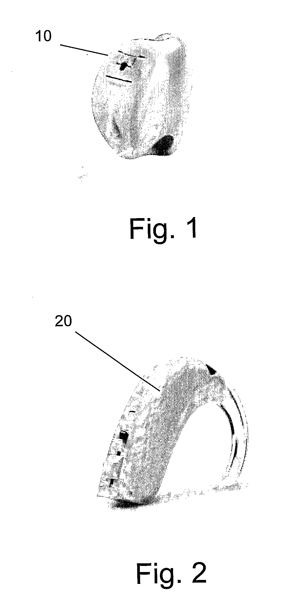
FIG. 1 illustrates a typical In-The-Ear (ITE) type hearing aid 10 of the prior art. FIG. 2 similarly illustrates a Behind-The-Ear (BTE) type hearing aid 20 of the prior art.

As mentioned, the small size of hearing aids, especially those placed within the ear, prevents incorporating high-quality FM communication capability within them, since such capability requires an antenna which is substantially larger than the size of the hearing aid itself and the need to accommodate for continuous changes in orientation of the hearing aid relative to the transmitter.

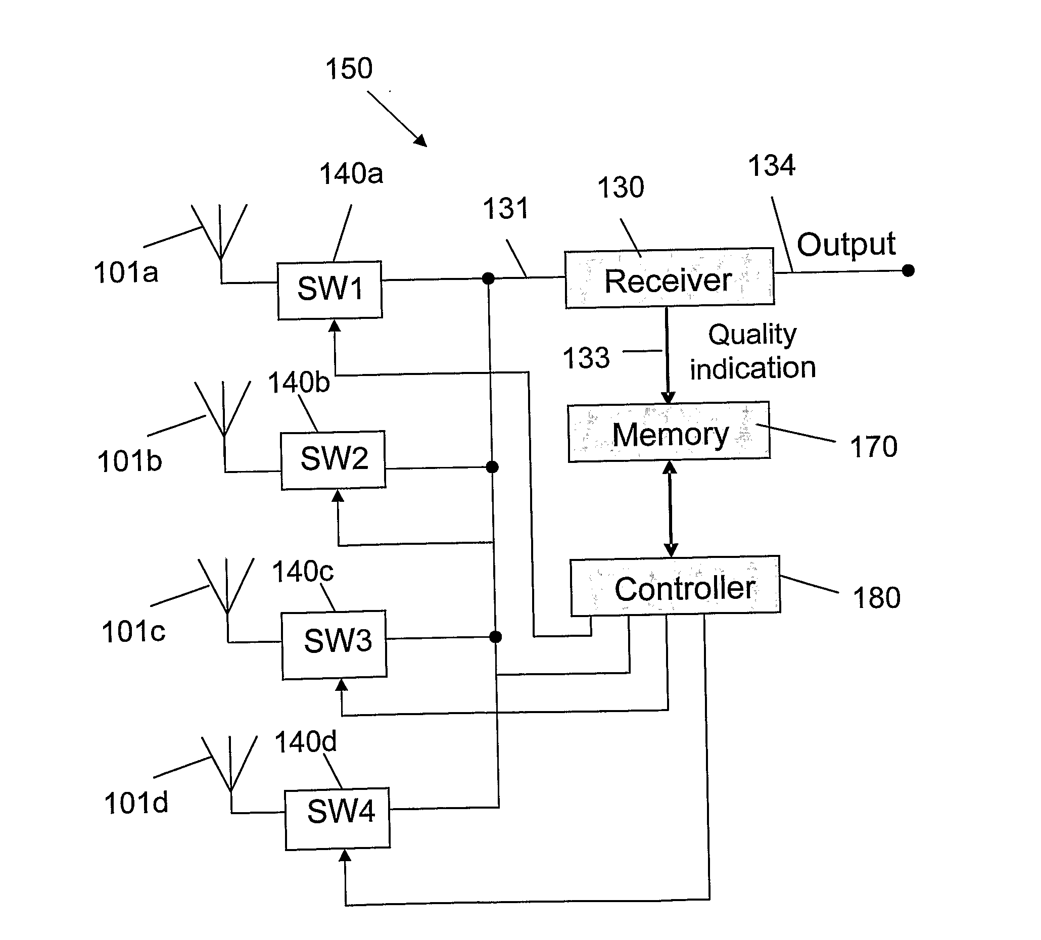
The present invention enables the incorporation of high quality RF communication, in all types of hearing aids. More specifically, the invention provides a mechanism and an improved structure for a hearing aid, which improves the device communication quality, while meeting all the requirements and limitations relating to the size, structure, and location of device.

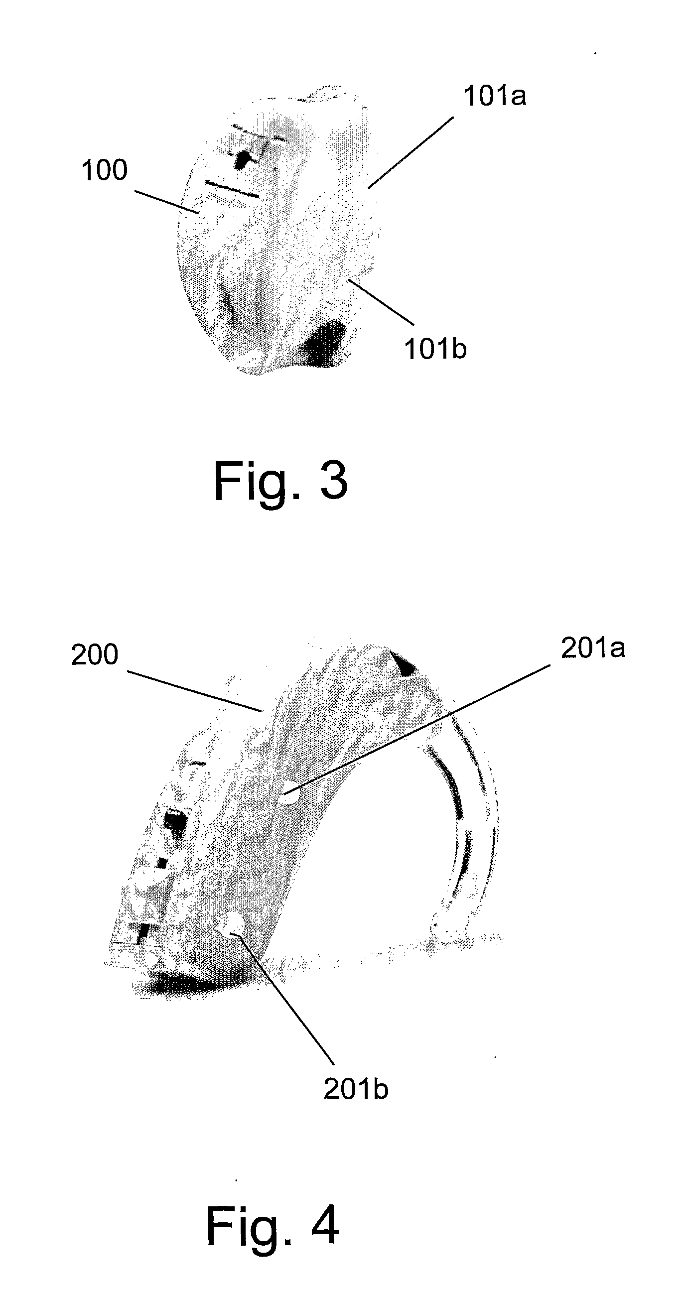
FIG. 3 shows an ITE type hearing aid 100, according to an embodiment ...


PUM


Abstract

The present invention relates to a hearing instrument which comprises: (a) a housing; (b) an RF receiver; (c) plurality of conductive elements, each conductive element has the form of a plate, is positioned on said housing so it provides coupling with the device wearer's skin while the instrument is in use, thereby forming an antenna element together with the wearer's body; (d) a switch for each conductive element, for connecting or disconnecting the respective antenna element from the receiver; (e) a controller for periodically initiating a testing cycle wherein during said cycle: (e.1) the controller sequentially scans said switches by closing each time another switch, thereby to connect each time a respective antenna element to said receiver; (e.2) each time said antenna switching is performed and a specific antenna element is connected to the receiver, the controller samples and stores a respective quality indication signal which is indicative of the quality of the received signal by said receiver via said respective antenna; (e.3) the controller inspects all said stored indications, determines from all said stored indications the one that relates to a best quality signal, and connects the antenna element which corresponds to said best quality signal to said receiver for a time duration which is substantially longer than the duration of said testing cycle, until performance of a next testing cycle.

Description

FIELD OF THE INVENTIONThe field of the invention relates in general to the field of hearing aids and hearing devices. More specifically the invention relates to an antenna arrangement for a hearing aid or hearing device which receives or transmits radio frequency (RF) signals.BACKGROUND OF THE INVENTIONA hearing aid or hearing device (hereinafter, both types will be referred to by the conclusive terms “hearing instruments”, or “hearing aids”) that contains RF receiver allows the user to receive sound from a remote source by means of RF communication. Some listening situations are more difficult than others for users of hearing instruments due to background noise or distance of the sound source. In such situations, wireless hearing instruments, also known as “FM systems” and “Assistive Listening Devices” (ALDs) are used in conjunction with the person's hearing aid. An FM system consists of a transmitter microphone located near the sound source and an FM receiver used by the listener....

Claims


Application Information

Patent Timeline
Patent Type & Authority Applications(United States)
IPC IPC(8): H04R29/00
CPCH01Q1/273H01Q9/0407H04R2225/51H04R25/554H04B7/0808
Inventor LEIBMAN, VADIMAHARON, EYAL
Owner AUDIODENT ISRAEL
Why Eureka
Try Eureka