
Image forming apparatus

a technology of image forming apparatus and forming apparatus, which is applied in the direction of electrographic process apparatus, instruments, optics, etc., can solve the problems of increased cost, increased defect image, and increased image quality, so as to reduce or prevent a decrease in image quality and less was

Inactive Publication Date: 2011-01-27
CANON KK
View PDF6 Cites 0 Cited by
  • Summary
  • Abstract
  • Description
  • Claims
  • Application Information

AI Technical Summary

Benefits of technology

The present invention provides an image forming apparatus that can reduce or prevent image quality degradation caused by contamination of the exposure system while being smaller in size and meeting environmental requirements for energy saving and less waste toner. The apparatus includes a photosensitive member, an exposure device, a development device, and a transfer device. The average current amount of developer after the developer image has been formed on the photosensitive member is between 50 μC / g and 90 μC / g, and the contact angle of the photosensitive member with respect to pure water is not less than 90° and not more than 150°.

Problems solved by technology

However, for example, Japanese Patent Application Laid-Open No. 11-184216 discusses that in a case where a proximity exposure system is combined with a CLN-less system, since toner exists and passes through the photosensitive member in an exposure unit, the toner adheres to the exposure unit, resulting in defective images.
If an electric charge amount of the toner passing through the exposure unit is small, the toner is likely to scatter and adhere to the optical system, so that occurrence of defective images with density non-uniformity may increase.
When the toner is prevented from adhering to the exposure unit by providing a developer charge amount control unit between after the transfer processing and before charging processing, the system needs to be enlarged, resulting in an increase in cost.
Since there is a limit to increase the charge amount of the residual transfer toner, there are not only contamination of the charging member but also adhesion of toner to the exposure unit and effects of preventing or reducing the generation of defective images are insufficient.
However, if the average charge amount of a developed image is set at as high as not less than 50 μC / g and not higher than 90 μC / g, the developed image cannot be readily transferred from the photosensitive member to paper in the transfer processing.

Method used


Image

  • Image forming apparatus
  • Image forming apparatus
  • Image forming apparatus

Examples


Embodiment Construction

[0029]Various exemplary embodiments, features, and aspects of the invention will be described in detail below with reference to the drawings.

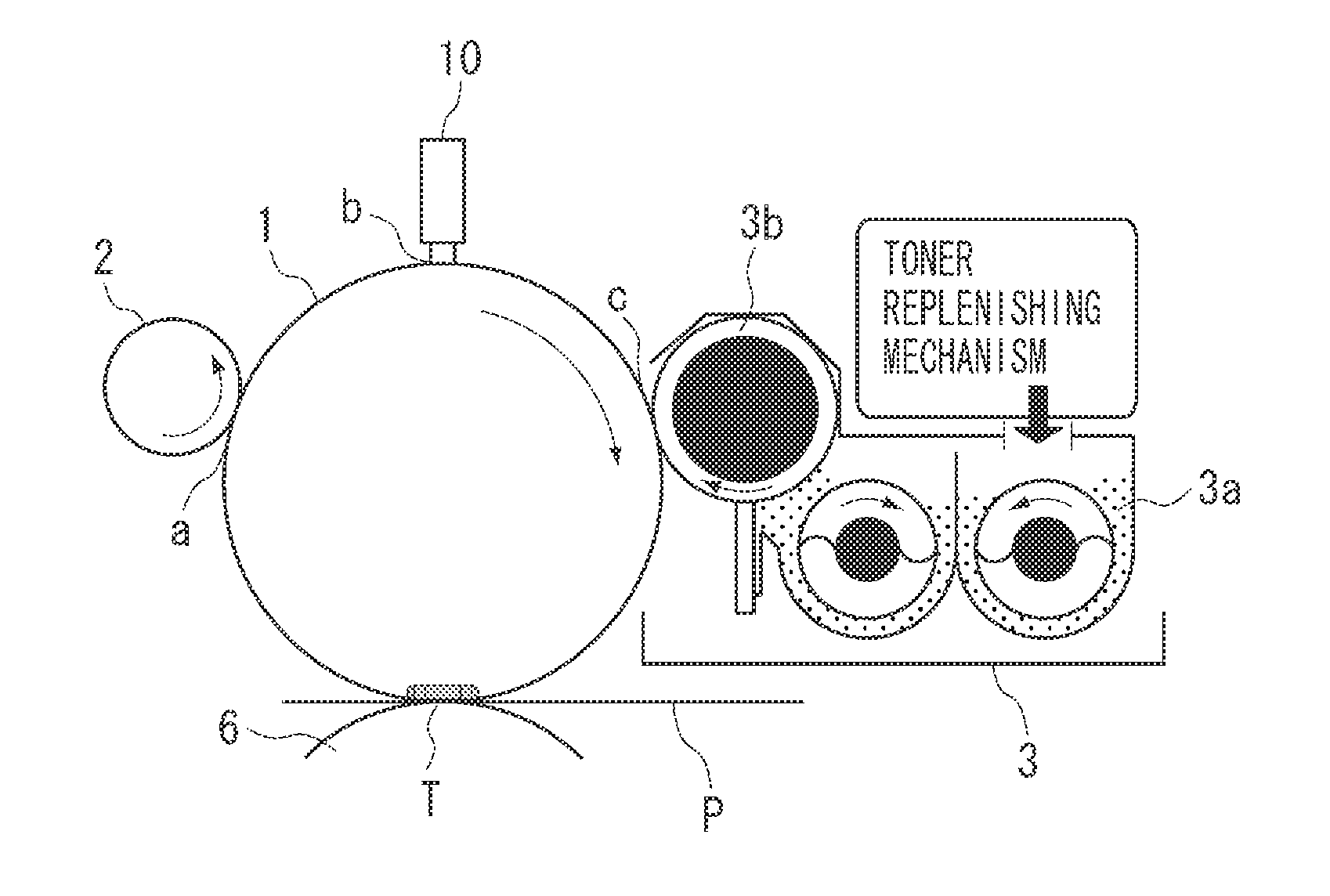
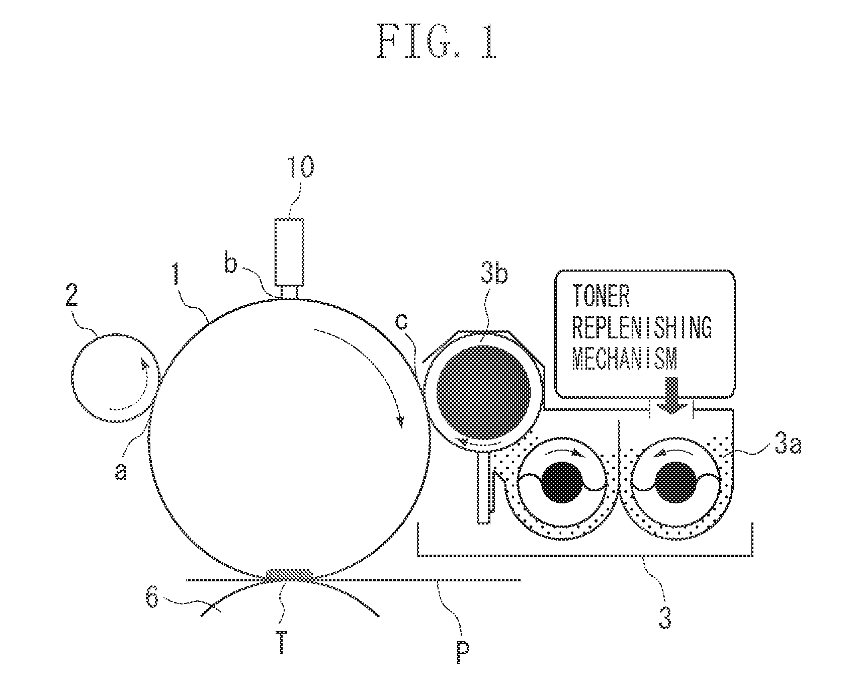
[0030]FIG. 1 is a sectional view of principal parts of an image forming apparatus according to a first exemplary embodiment of the present invention. The illustrated image forming apparatus is an LED printer that uses a transfer method electrophotographic process, adopts a contact charging method, a reversal development method, and a cleaner-less structure, and handles a maximum sheet size of A3. The image forming apparatus performs a series of processing, including charging, exposure, and development on a photosensitive drum 1 as a photosensitive member to form a toner image (developer image) thereon based on image data. The developer image is transferred to an intermediate transfer belt as an intermediate transfer member, and a transferred image is further transferred to recording paper as a transfer material. The toner image on the recording...


PUM


Abstract

A cleaner-less image forming apparatus includes an LED which is arranged with a closest distance of 10 to 5000 μm to a photosensitive member and exposes the photosensitive member. In the image forming apparatus, an absolute value of an average current amount of a developer is between 50 μC / g and 90 μC / g, and a contact angle of the photosensitive member with respect to pure water is not less than 90° and not more than 150°.

Description

BACKGROUND OF THE INVENTION[0001]1. Field of the Invention[0002]The present invention relates to an electrophotographic image forming apparatus.[0003]2. Description of the Related Art[0004]In recent years, from a viewpoint of compactness, low in cost, and concern for the environment, a demand for an image forming apparatus which consumes less energy and produces less waste toner has increased. Compared with a conventional laser optical system, a light-emitting diode (LED) exposure system has a short optical path and contributes to a miniaturization of a main body of the system. Further, it does not need a polygon motor, so that energy consumption can be reduced. At present, however, LEDs need to be located close to an object to be exposed on account of light quantity. Therefore, a close proximity exposure system is adopted. In an ordinary electrophotographic operation, a surface of a photosensitive member is electrostatically charged and exposed to form a latent image, and after the...

Claims


Application Information

Patent Timeline
Patent Type & Authority Applications(United States)
IPC IPC(8): G03G15/00G03G15/08
CPCG03G15/326G03G15/04054G03G2215/0409G03G21/0064
Inventor TAKEDA, ATSUSHI
Owner CANON KK
Features
  • Generate Ideas
  • Intellectual Property
  • Life Sciences
  • Materials
  • Tech Scout
  • Unparalleled Data Quality
  • Higher Quality Content
  • 60% Fewer Hallucinations
Learn More