
Internal combustion engine and vehicle

a combustion engine and internal combustion technology, applied in machines/engines, valve arrangements, cylinders, etc., can solve the problems of reducing or preventing attenuating surging, and unlikely surging, so as to reduce or prevent a decrease in fuel efficiency, reduce the size or weight of the rocker arm, and increase the size of the variable valve mechanism

Active Publication Date: 2021-07-20
YAMAHA MOTOR CO LTD
View PDF11 Cites 0 Cited by
  • Summary
  • Abstract
  • Description
  • Claims
  • Application Information

AI Technical Summary

Benefits of technology

The patent provides a way to make internal combustion engines that use less fuel, are smaller, and are less likely to have problems when running at high speeds. They also make it possible to reduce the size or weight of the part that controls the valve timing, and to have a smaller or lighter rocker arm. This makes it easier to make vehicles that use less fuel and are more efficient.

Problems solved by technology

Thus, the switchable range of the valve operation state will not be narrowed, thus significantly reducing or preventing a decrease in the fuel efficiency.
Moreover, the compression coil spring is able to come into contact with the shaft, and when surging is about to occur while the internal combustion engine is running at a high speed, the compression coil spring and the shaft come into contact with each other, thus attenuating the surging.
Thus, surging is unlikely to occur while running at a high speed.

Method used


Image

  • Internal combustion engine and vehicle
  • Internal combustion engine and vehicle
  • Internal combustion engine and vehicle

Examples


Embodiment Construction

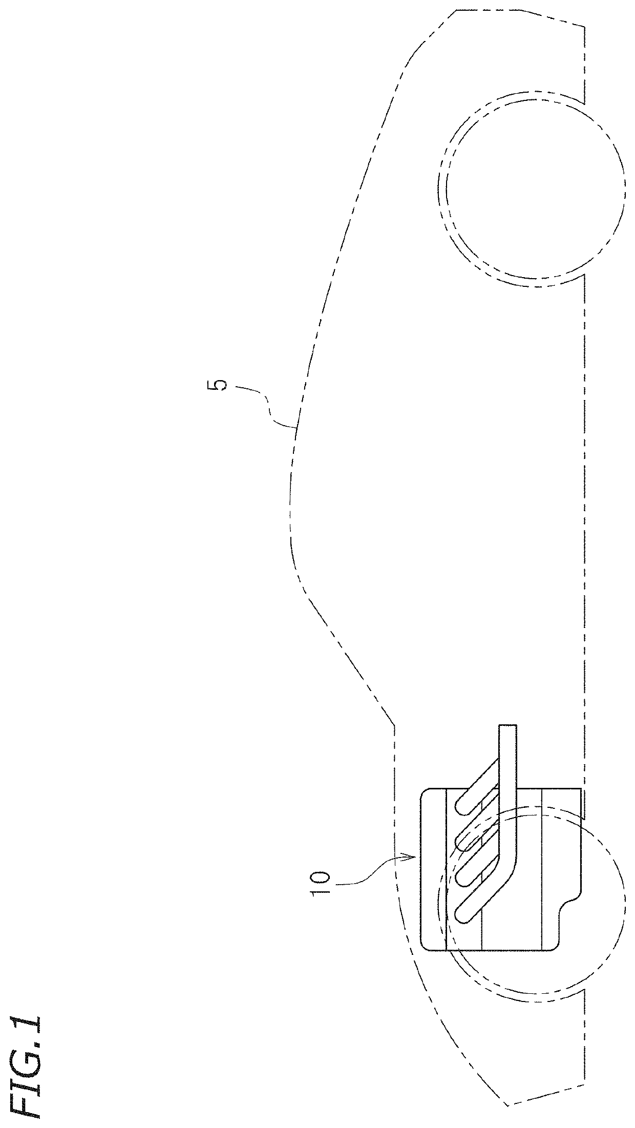
[0045]Preferred embodiments of the present invention will now be described with reference to the drawings. An internal combustion engine according to the present preferred embodiment is installed in a vehicle and used as the drive source of the vehicle. There is no limitation on the type of the vehicle, which may be a straddled vehicle such as a motorcycle, an auto tricycle or an ATV (All Terrain Vehicle) or may be an automobile. For example, an internal combustion engine 10 may be provided in the engine room of an automobile 5 as shown in FIG. 1.

[0046]The internal combustion engine 10 according to the present preferred embodiment is preferably a multi-cylinder engine including a plurality of cylinders. The internal combustion engine 10 is a 4-stroke engine that goes through the intake stroke, the compression stroke, the combustion stroke, and the exhaust stroke. FIG. 2 is a partial cross-sectional view of the internal combustion engine 10. As shown in FIG. 2, the internal combustio...


PUM


Abstract

An internal combustion engine includes, as a lost motion spring that urges a rocker arm toward a cam, a compression coil spring supported on a cylinder head. A shaft is located on an inner side of the compression coil spring and extends along a winding axis of the compression coil spring. The internal combustion engine significantly reduces or prevents a decrease in the fuel efficiency and an increase in the size of the variable valve mechanism, while surging is unlikely to occur while running at a high speed, and it is possible to reduce the size or the weight of the rocker arm.

Description

BACKGROUND OF THE INVENTION1. Field of the Invention[0001]The present invention relates to an internal combustion engine and a vehicle.2. Description of the Related Art[0002]There are conventional internal combustion engines that have a variable valve mechanism wherein the valve operation state can be switched, as disclosed in Japanese Laid-Open Patent Publication No. 2009-185753, for example. A variable valve mechanism has a rocker arm including a first arm pivotally supported on a cylinder head and a second arm pivotally supported on the first arm, and a connecting mechanism that removably connects the first arm and the second arm. The first arm includes an abutting portion that abuts the valve. The second arm includes a contact portion that contacts with a cam provided on a cam shaft. When the first arm and the second arm are connected by the connecting mechanism, the second arm pivots as a single unit together with the first arm. Therefore, when the cam presses the contact porti...

Claims


Application Information

Patent Timeline
IPC IPC(8): F01L1/18F01L1/053F01L1/46F02F1/24
CPCF01L1/181F01L1/053F01L1/462F02F1/24F01L2001/467F01L1/18F01L1/185F01L13/00F01L13/0005F01L13/0036
Inventor OKAMOTO, YASUO
Owner YAMAHA MOTOR CO LTD
Features
  • Generate Ideas
  • Intellectual Property
  • Life Sciences
  • Materials
  • Tech Scout
  • Unparalleled Data Quality
  • Higher Quality Content
  • 60% Fewer Hallucinations
Learn More