
Method of Estimating the Volume of a Pressurized Gas Container

a technology of pressurized gas and volume estimation, which is applied in the direction of pressure vessels, containers discharging from pressure vessels, and containers filled under pressure, etc., can solve the problems of inability or inadequacies to measure the pressure and temperature inside the tank, the volume estimation method has drawbacks, and the quantity of gas in the tank cannot be known with sufficient precision

Inactive Publication Date: 2011-01-27
LAIR LIQUIDE SA POUR LETUDE & LEXPLOITATION DES PROCEDES GEORGES CLAUDE
View PDF5 Cites 28 Cited by
  • Summary
  • Abstract
  • Description
  • Claims
  • Application Information

AI Technical Summary

Benefits of technology

[0063]the connection from the tank to the source includes at least one gas transfer control valve and the step of determining the quantity (Q=ntk(t2)−ntk(t1)) of gas transferred from the source into the tank during flow of the checking stream comprises an estimation of the flow passing through the valve as a function of its degree

Problems solved by technology

In addition, it is generally not possible or not appropriate to measure the pressure and the temperature inside the tank.
However, the volume estimated using this method has drawbacks.
In addition, the gas density estimated according to the above document does not enable the quantity of gas in the tank to be known with sufficient precision.
This method has the same drawbacks as those discussed above (inappropriate measurements in the tank).
Thus, this method cannot be used for a tank of unknown volume.

Method used


Image

  • Method of Estimating the Volume of a Pressurized Gas Container
  • Method of Estimating the Volume of a Pressurized Gas Container
  • Method of Estimating the Volume of a Pressurized Gas Container

Examples


Embodiment Construction

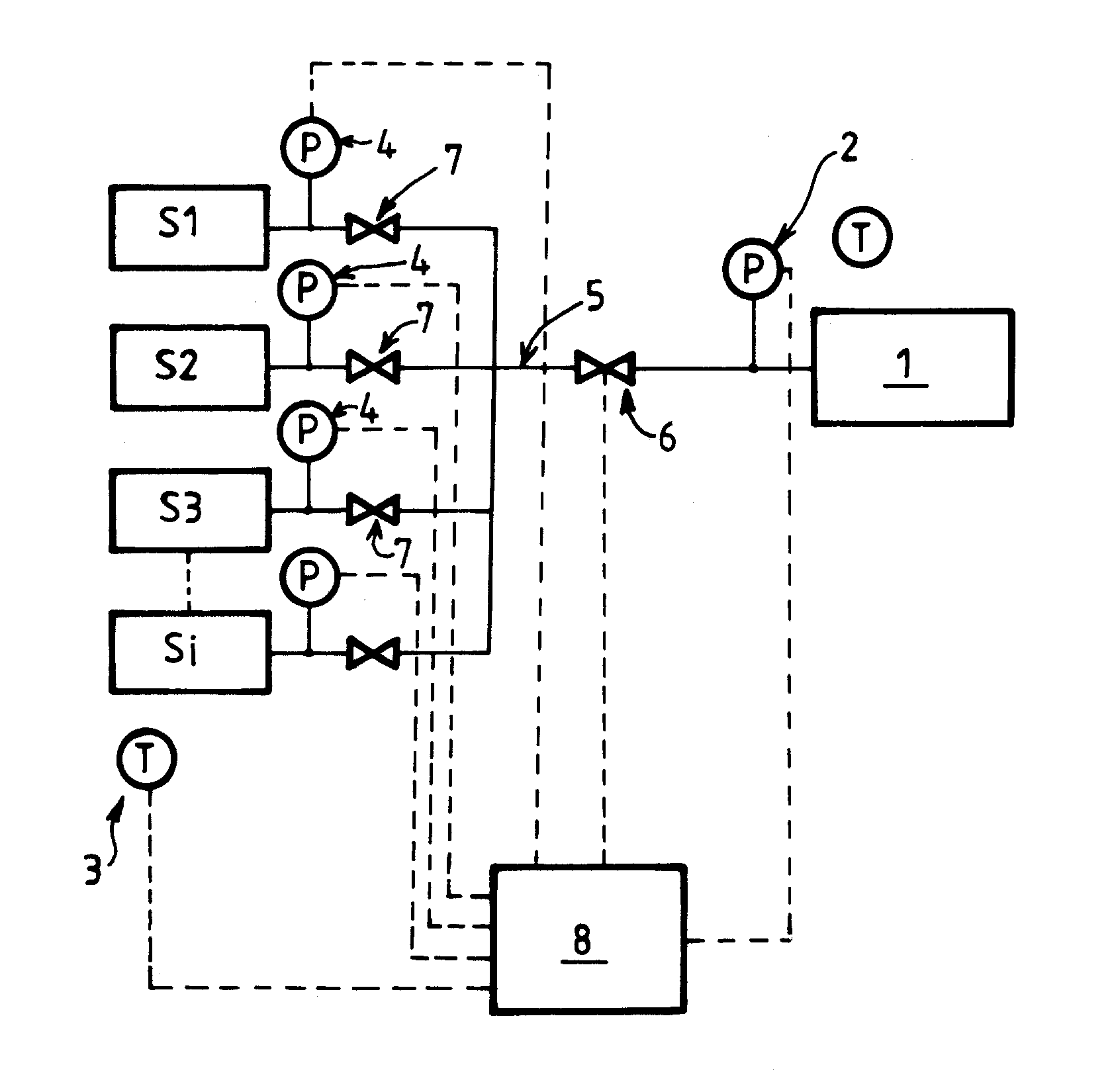
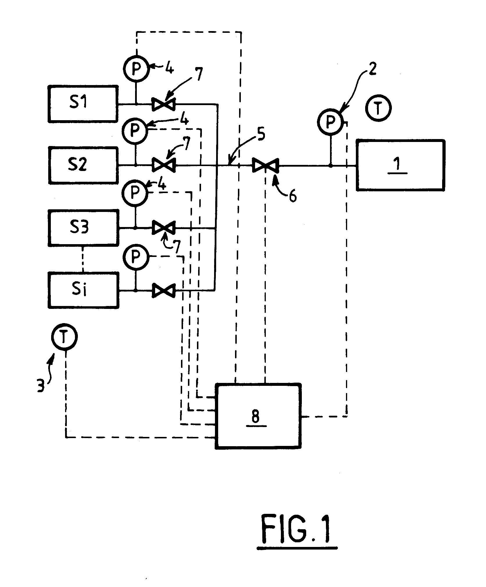
[0069]As shown in FIG. 1, the method may be implemented by a filling station comprising, for example, several pressurized gas source containers S1, S2, . . . , Si. Conventionally, the containers S1 to Si my be used for filling a tank 1 by pressure balancing (“in cascade”, i.e. using several containers having successively higher storage pressures). As a variant, or additionally, the station may use a gas compressor or any means capable of delivering gas at high pressure (for example between 200 and 850 bar). The source containers S1 to Si are connected in parallel to a common filling line 5 that can be selectively connected to one or more tanks to be filled. Respective valves 7 may be provided for controlling the supply of gas from the containers S1 to Si to the common line 5. In addition, one or more valves 6 may be provided for controlling the flow of gas in the line 5. An electronic control software 8 may be provided for carrying out all or some of the process.

[0070]To calculate o...


PUM

PropertyMeasurementUnit
Pressureaaaaaaaaaa
Pressureaaaaaaaaaa
Pressureaaaaaaaaaa

Abstract

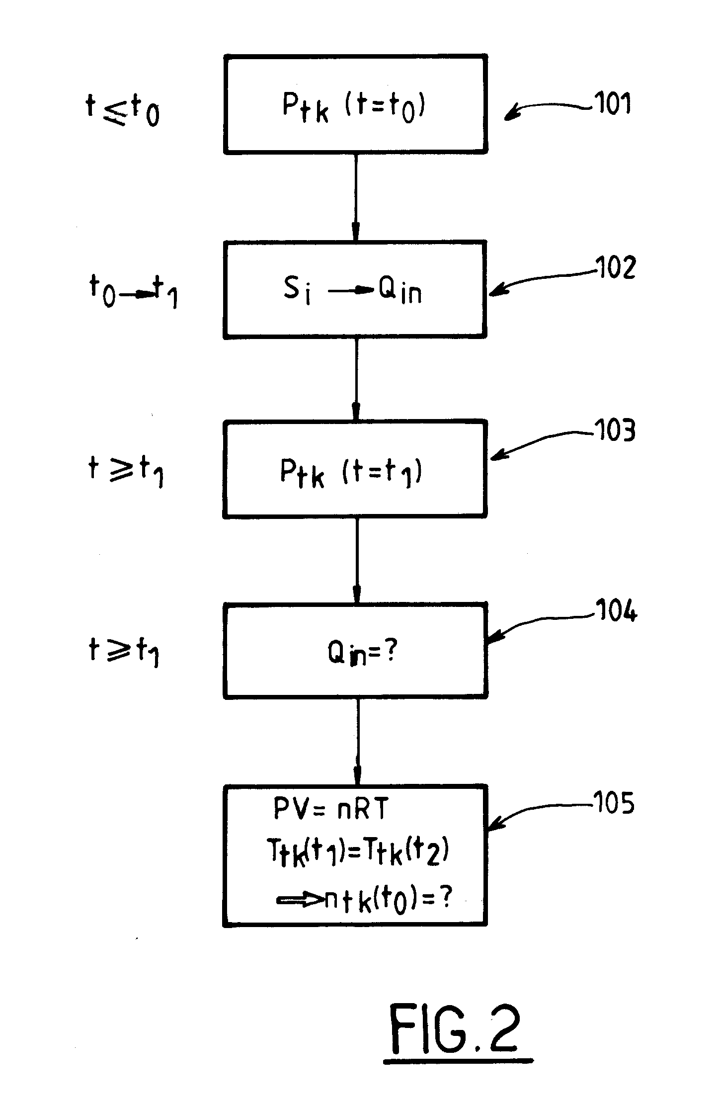
Method of estimating the volume (Vtk) of a tank (1), comprising:a first step of determining the quantity (ntk(ti)) of gas contained in the tank (1) at a first time (t=t1); thena step of transferring a checking stream of gas from a source (S1, S2, S3, . . . , Si) into the tank (1), the checking stream flowing over a discrete period (t2−t1);a step of determining the quantity (Q=ntk(t2)−ntk(t1)) of gas transferred from the source (S1, S2, S3, . . . Si) into the tank (1) during flow of the checking stream of gas; anda step of calculating the volume (Vtk) of the tank (1) by applying the law of conservation of enthalpy (H) of the gas, considering that the transfer of the checking stream of gas is adiabatic (Ttk(t1)=Ttk(t2) and Tsi(t1)=Tsi(t2)), expressing the enthalpy of the gas in the tank as a function only of the temperature Ttk(ti) of the gas and the pressure Ptk(ti) of the gas (Htk=function of (Ttk(ti); Ptk(ti)), using the perfect gas law or a Van der Waals equation of state expressing the volume of the tank Vtk(ti) (in cubic metres) only as a function of the known or previously estimated variables.

Description

CROSS-REFERENCE TO RELATED APPLICATIONS[0001]This application claims the benefit of priority under 35 U.S.C. §119(a) and (b) to French Application No. 0955230, filed Jul. 27, 2009, the entire contents of which are incorporated herein by reference.BACKGROUND[0002]1. Field of the Invention[0003]The present invention relates to a method of estimating the volume of a pressurized gas tank.[0004]The invention may especially be used in a station for filling bottles or tanks with pressurized gas.[0005]Advantageously, the invention may be applied in stations for filling vehicles with gaseous fuel (especially hydrogen).[0006]2. Related Art[0007]Stations for filling gas tanks for motor vehicles powered by hydrogen are generally adapted to one or more defined types of tanks to be filled.[0008]This is because it is important to know the volume of the tank to be filled in order to achieve optimized filling, safe from the point of view of safety.[0009]In addition, it is generally not possible or n...

Claims


Application Information

Patent Timeline
IPC IPC(8): G01F23/14
CPCF17C5/06Y02E60/321F17C13/023F17C13/025F17C13/026F17C13/028F17C2221/012F17C2223/0123F17C2223/036F17C2225/0123F17C2225/036F17C2227/043F17C2250/032F17C2250/043F17C2250/0439F17C2250/0443F17C2250/0491F17C2250/0495F17C2250/0615F17C2250/0621F17C2250/0694F17C2260/025F17C2265/065F17C2270/0139F17C7/00Y02E60/32G01F17/00G01F22/02
Inventor MACRON, JONATHANDAMONGEOT, LOIC
Owner LAIR LIQUIDE SA POUR LETUDE & LEXPLOITATION DES PROCEDES GEORGES CLAUDE
Learn More