Die carrier assembly and crimping process

Active Publication Date: 2011-02-03
CONTITECH USA INC
View PDF6 Cites 17 Cited by
  • Summary
  • Abstract
  • Description
  • Claims
  • Application Information

AI Technical Summary

Problems solved by technology

While the die carrier assembly 14 represented in FIGS. 1 through 6 is adequate for many applications, limitations can be encountered if the hose or other component to be crimped has an elbow or another geometric shape or feature that results in the component having other than a uniform circular outer perimeter that is continuous along the length of

Method used


Image

  • Die carrier assembly and crimping process
  • Die carrier assembly and crimping process
  • Die carrier assembly and crimping process

Examples


Embodiment Construction

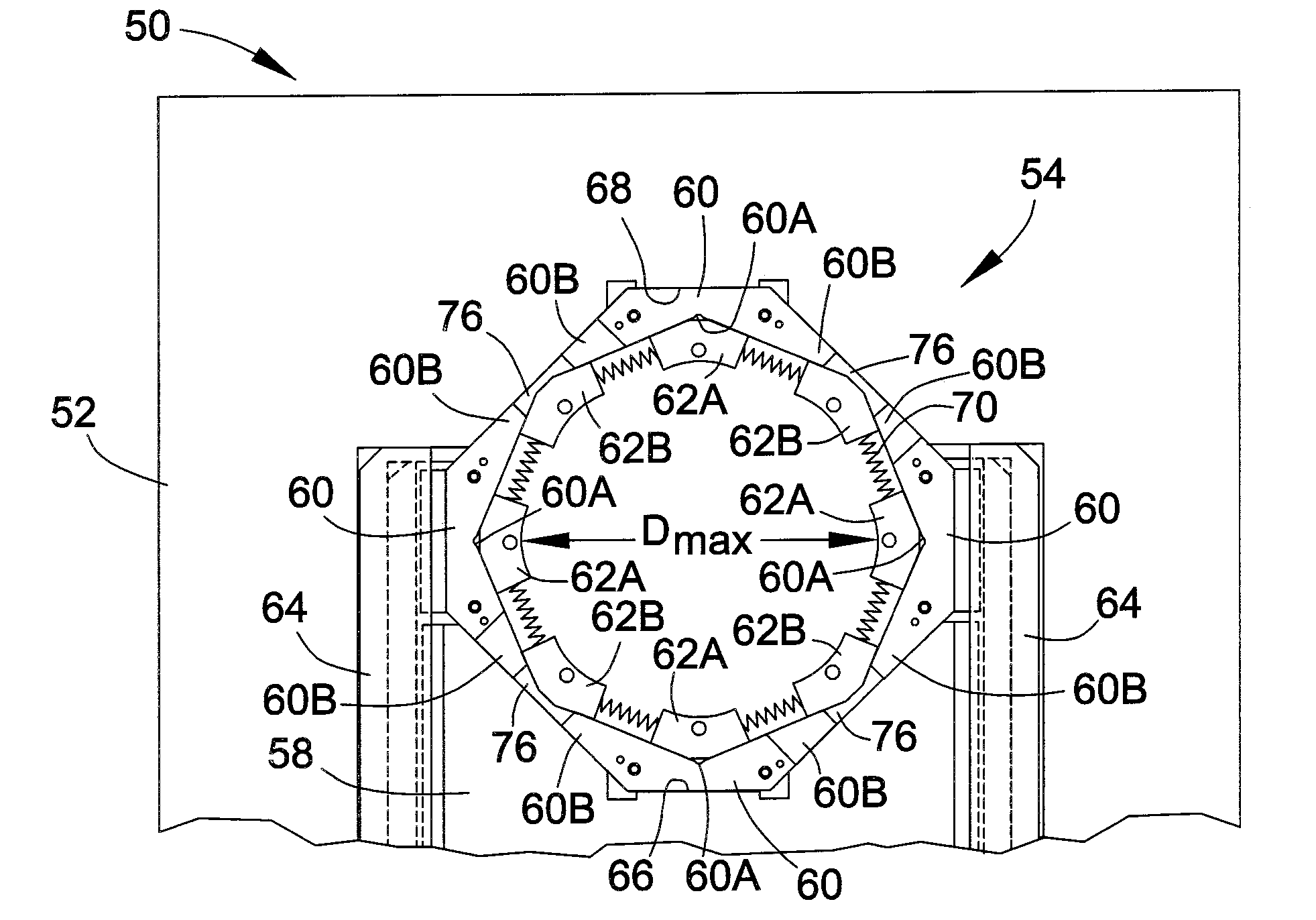
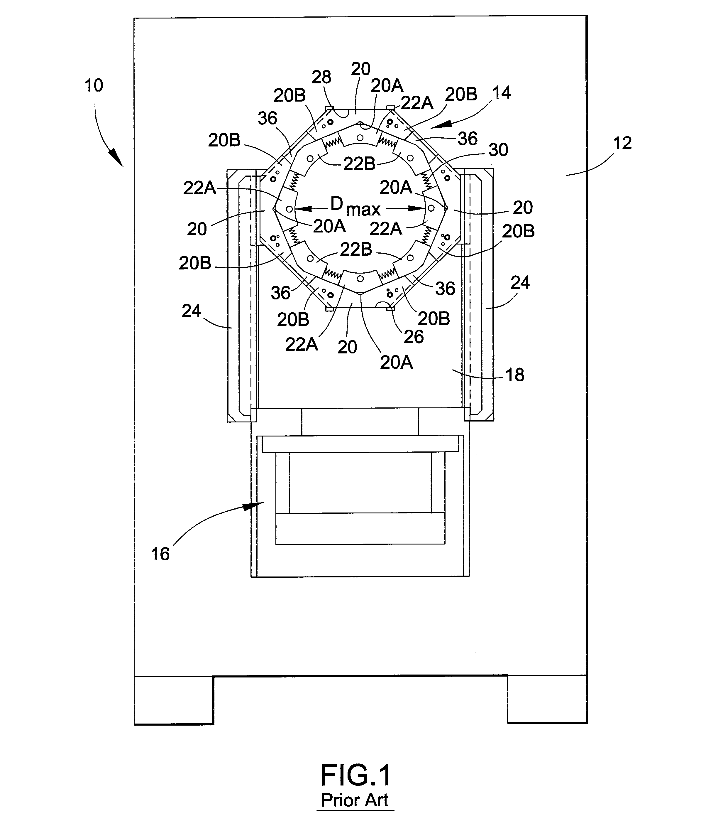
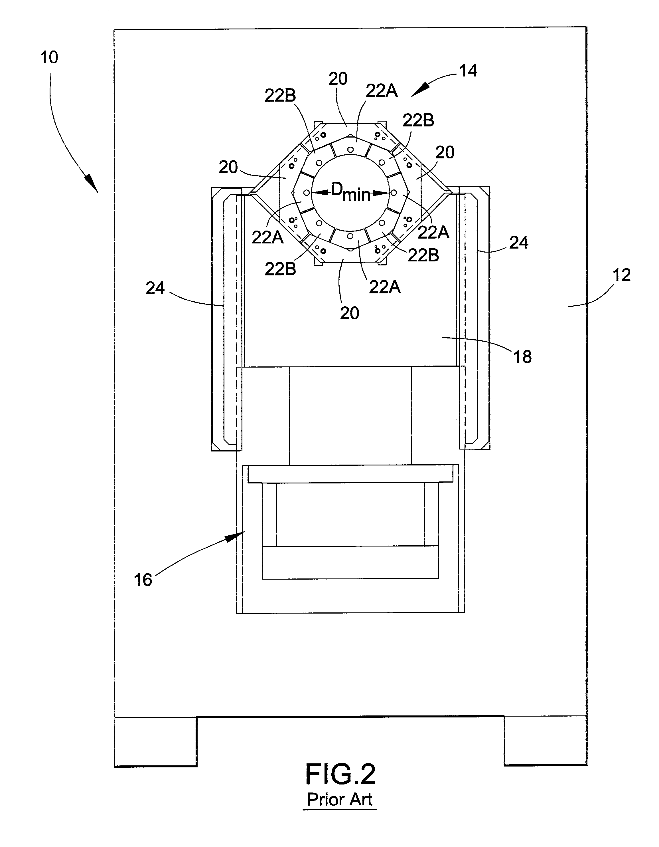
[0023]A die carrier assembly 54 representative of an embodiment of this invention is depicted in FIGS. 7 and 8, and components of the die carrier assembly 54 are represented in isolation in FIGS. 9 through 12. The die carrier assembly 54 can be used in a crimping machine of the type represented in FIGS. 1 and 2, as well as other machines with various other configurations. As will become evident from the following discussion, the die carrier assembly 54 is configured to allow greater die carrier travel and a larger maximum opening for the same footprint of an existing crimping machine.

[0024]To facilitate the description of the die carrier assembly 54 and its installation and use in a crimping machine, the terms “vertical,”“horizontal,”“upper,”“lower,”“above,”“below,” etc., will be used in reference to the perspective of the orientation shown in FIGS. 7 through 12, and therefore are relative terms and should not be interpreted as otherwise limiting the scope of the invention.

[0025]Sim...


PUM

PropertyMeasurementUnit
Perimeteraaaaaaaaaa

Abstract

A die carrier assembly configured for use in a crimping machine. The assembly includes die carriers disposed in a circumferential arrangement and adapted for radially inward and outward travel. Each die carrier has oppositely-disposed circumferential extents that define circumferential gaps between adjacent pairs of the die carriers. Shoes are disposed radially inward from the die carriers and are adapted for radially inward and outward travel with the die carriers. The shoes travel radially inward and outward with the die carriers between positions in which the shoes define minimum and maximum openings, respectively, of the die carrier assembly. At least one of the shoes is disposed radially inward from one of the circumferential gaps between at least one adjacent pair of the die carriers. The circumferential extents of the adjacent pair of die carriers define interdigitated fingers that support the shoe when the die carrier assembly is at its maximum opening position.

Description

CROSS REFERENCE TO RELATED APPLICATIONS[0001]This application claims the benefit of U.S. Provisional Application No. 61 / 146,703, filed Jan. 23, 2009, the contents of which are incorporated herein by reference.BACKGROUND OF THE INVENTION[0002]The present invention generally relates to crimping machines that utilize interacting die segments adapted to radially travel toward each other to diametrically crimp components together, such as a fitting to a hose. More particularly, this invention relates to a crimper assembly configured to increase the radial travel capability of its die segments and thereby increase the size of the opening that can be defined by the die segments during loading of the crimper assembly with components to be crimped.[0003]Crimping machines adapted to crimp fittings, ferrules, etc. to hoses, pipes and other components are well known. A notable example is the CustomCrimp® CC Series of crimping machines, which are available in a variety of sizes to crimp hoses wi...

Claims


Application Information

Patent Timeline
IPC IPC(8): B21D39/04B21D41/04
CPCY10T29/5367B21D39/048
Inventor INTAGLIATA, JOSEPH V.RUGE, JOSHUA T.
Owner CONTITECH USA INC
Why Eureka
Try Eureka