Automated calibration of a surveying instrument

a geodetic instrument and automatic calibration technology, applied in the field of geodetic instruments and methods for calculating geodetic instruments, can solve the problems of high requirements on mechanical stability, limited accuracy and reliability of measurements, and deviations contributing to errors, so as to simplify the design of geodetic instruments and reduce the requirement on mechanical stability of instruments. , the effect of reducing the requirement of mechanical stability

Active Publication Date: 2011-02-03
TRIMBLE INC
View PDF13 Cites 121 Cited by
  • Summary
  • Abstract
  • Description
  • Claims
  • Application Information

AI Technical Summary

Benefits of technology

[0028]The present invention achieves a number of advantages. For instance, the geodetic instrument and method of the present invention are advantageous in that the calibration of the instrument is performed when it objectively is needed and not according to the subjective evaluation of a user. With the present invention, calibration may be performed on a regular basis. In contrast, with prior art systems, a user may often recognize the need for calibration only when abnormal results are obtained, i.e. too late.
[0029]Further, the present invention is advantageous in that the geodetic instrument may be used without waiting for acclimatization of the instrument to ambient temperature or waiting during the period of time required by the instrument to warm up. Indeed, with the present invention, it is possible to perform a calibration during the increase in temperature of the instrument.
[0030]Further, the present invention is advantageous in that it simplifies the design of a geodetic instrument. Indeed, as the need for calibration is automatically detected, accuracy of the measurements is ensured by calibration and the requirements on mechanical stability of the instrument are reduced or at least relaxed.
[0031]Furt...

Problems solved by technology

This deviation εk represents a trunnion axis error of the total station 100, which deviation contributes to errors when aiming at targets out of the horizon.
However, a drawback of prior art methods and surveying instruments ...

Method used


Image

  • Automated calibration of a surveying instrument
  • Automated calibration of a surveying instrument
  • Automated calibration of a surveying instrument

Examples


Embodiment Construction

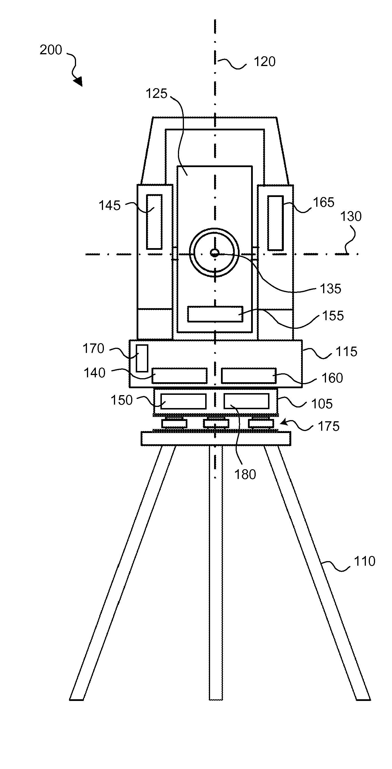
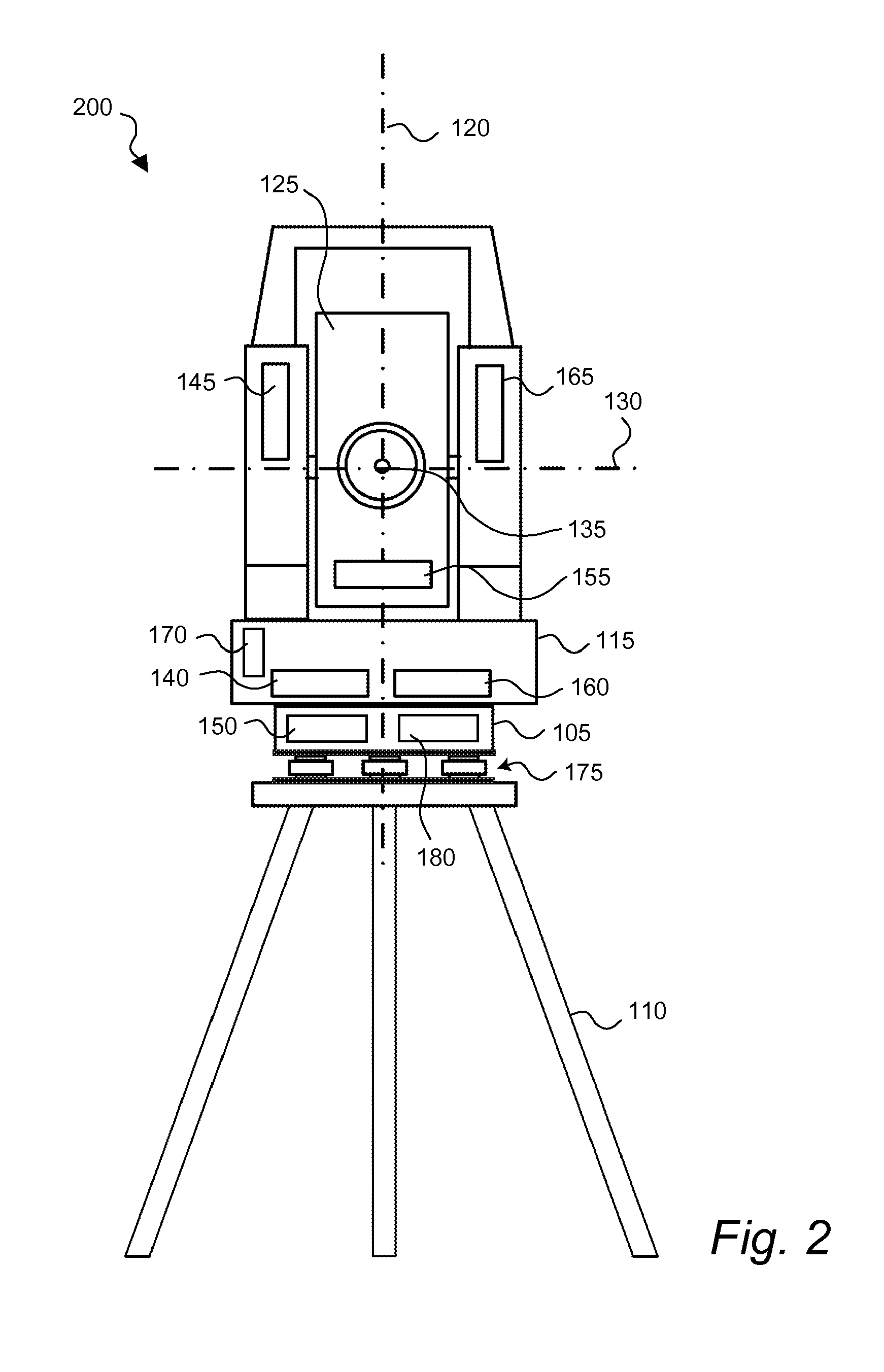
[0078]With reference to FIG. 2, a first embodiment of the present invention will be described below.

[0079]A geodetic instrument, for example a total station, is schematically shown in FIG. 2. The total station 200 comprises a base 105, an alidade 115 mounted on the base for rotation about a vertical axis 120 and a center unit 125 mounted on the alidade for rotation about a horizontal axis 130. The total station 200 further comprises a processing unit 150 and at least one detector 170.

[0080]In the present embodiment, the processing unit 150 is arranged at the base 105 of the total station 200. However, the processing unit 150 may also be arranged at e.g. the alidade 115 or the center unit 125 as long as a connection is established between the processing unit 150 and the detector 170. According to an embodiment, the processing unit 150 may be a remote unit which communicates with the detector 170 and other elements (units) of the total station 200 by wireless communication.

[0081]As sh...


PUM


Abstract

The present invention provides a method for calibrating a geodetic instrument, an instrument and a computer program product thereof. In the method and geodetic instrument of the present invention, a value of at least one parameter affecting the measurements made by the instrument is detected and compared with a predetermined threshold. On the basis of the comparison between the detected value and the predetermined threshold, the instrument aims at a reference target and a calibration is performed using the reference target. The present invention is advantageous in that the accuracy and reliability of the measurements performed by the instrument are increased. Further, the present invention is advantageous in that the requirements on mechanical stability are reduced.

Description

FIELD OF THE INVENTION[0001]The present invention generally relates to systems and methods for surveying. The present invention relates in particular to a method for calibrating a geodetic instrument, a geodetic instrument and a computer readable product thereof.BACKGROUND ART[0002]The art of surveying involves the determination of unknown positions, surfaces or volumes of objects using measurements of angles and distances. In order to make these measurements, a surveying instrument frequently comprises an electronic distance measurement unit (EDM unit) which may be integrated in a theodolite, thereby forming a so-called total station. A total station combines electronic, optical and computer techniques and is furthermore provided with a computer or control unit with writable information for controlling the measurements to be performed and for storing data obtained during the measurements. Preferably, the total station calculates the position of a target in a fixed ground-based coor...

Claims


Application Information

Patent Timeline
IPC IPC(8): G01C25/00
CPCG01C25/00G01C15/00
Inventor GRASSER, CHRISTIAN
Owner TRIMBLE INC
Why Eureka
Try Eureka