Flywheel

a technology of flanges and flanges, which is applied in the field of flanges, can solve the problems of composite ring failure, loose fit of outer ring, dangerous disassembly of central support sections, etc., and achieves the effects of reducing the size of the support element, increasing the safety of the fit, and increasing the achievable rotational speed

Inactive Publication Date: 2011-02-03
RICARDO UK LTD
View PDF44 Cites 16 Cited by
  • Summary
  • Abstract
  • Description
  • Claims
  • Application Information

AI Technical Summary

Benefits of technology

[0011]In this aspect of the invention, as the reinforcing element is radially outside the mass element it is able to support the mass element without the need for a substantial preload as the tendency for the rim to grow in diameter as the rotational speed increases and disengage the support element is reduced. As the flywheel rotational speed increases, the mass element tends to be forced towards the support element by centrifugal forces, thereby increasing t

Problems solved by technology

However, the outer ring can become a loose fit on the central support section and potentially (dangerously) become dismounted from the central support section.
In addition the radial stress can result in failure of the composite ring.
The mismatch in diameters results in a pre-load such that that ring exerts an inward force onto the central support section.
Consequently a large amount of material may be required in the central support section of the flywheel in order to counteract this pre-load force, and this material, being near the centre of the flywheel, adds only very inefficiently to the rotational inertia of the flywhe

Method used


Image

  • Flywheel
  • Flywheel
  • Flywheel

Examples


Embodiment Construction

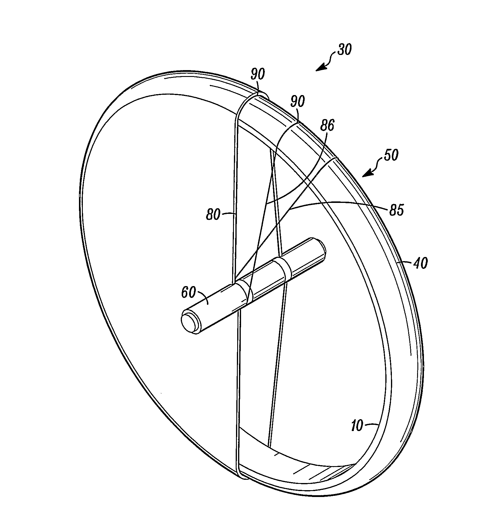
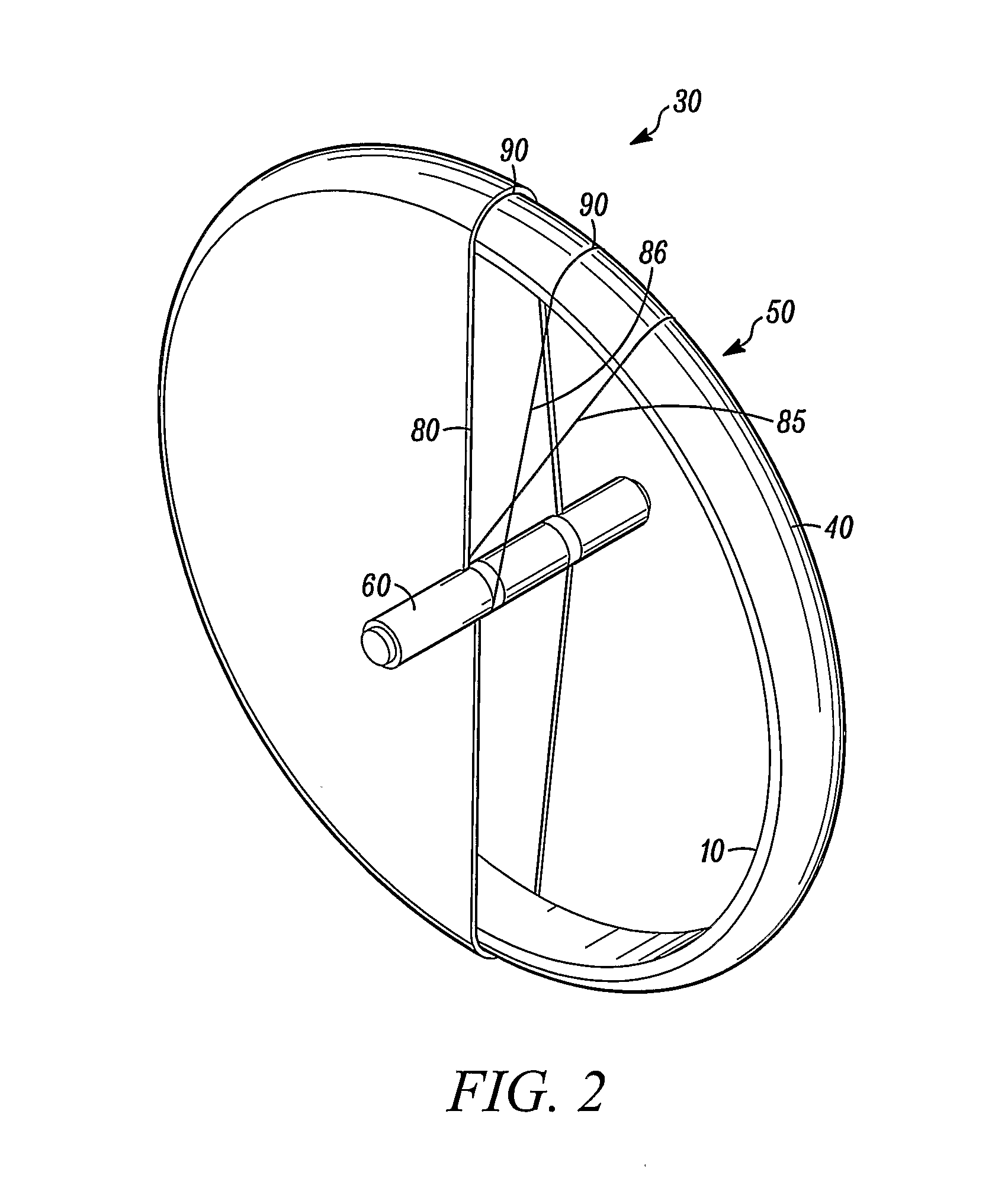
[0024]In overview, the apparatus and method described herein relates to a flywheel energy storage device where material used in its construction is deployed in an inertially efficient manner, and where the support structure is under tension, a rim comprising a mass element is held in place on its outer surface by a winding which also passes around a drive transfer element, rather than for example by a compressive interference fit to its inner surface.

[0025]In other aspects a support element can surround the rim to counteract centrifugal forces and a torsionally compliant or resilient drive transfer element such as shaft can be provided.

[0026]The winding may be configured in a number of ways as described below and may also be pre-tensioned. The drive transfer element may be a shaft, which may be hollow and may be constructed from wound carbon fibre. The rim may comprise a circumferential support member and a mass element mounted radially inwards of the support member.

[0027]In embodim...


PUM

PropertyMeasurementUnit
Massaaaaaaaaaa
Speedaaaaaaaaaa
Circumferenceaaaaaaaaaa

Abstract

The invention relates to an apparatus and method for constructing a flywheel for energy storage, the flywheel having a drive transfer element (60) and a rim comprising a mass element (10), the drive transfer element being coupled to the rim by a winding (80) around each.

Description

[0001]The invention relates to an apparatus and method for constructing a flywheel for energy storage.BACKGROUND OF THE INVENTION[0002]Flywheels are known for the storage of energy in the form of kinetic energy, for example for use in vehicles. In such instances it is known to use a flywheel to store the energy which would otherwise be converted to heat in the vehicle's braking system when the vehicle decelerates, this stored energy then being available for use to accelerate the vehicle when desired.[0003]A known type of flywheel according to FIG. 1 has a central metallic support section (1) which can be mounted on a central support such as a shaft. At least one composite ring (2) is mounted on the central support section. The composite ring in this type of flywheel is filament wound from carbon fibre. When the flywheel is in rotation, the ring will tend to expand in diameter due to the centrifugal forces acting on it. The ring has high strength in hoop for re-acting the centrifugal...

Claims


Application Information

Patent Timeline
IPC IPC(8): F16F15/305B21C47/04B32B37/16B23P11/00F16C15/00
CPCF16C15/00F16F15/3153Y10T74/1296Y10T29/49826Y02E60/16F16C2361/55
Inventor ATKINS, ANDREWCHILD, MATTHEW
Owner RICARDO UK LTD
Why Eureka
Try Eureka