Solar receiver for a solar concentrator with a linear focus

a solar concentrator and solar receiver technology, applied in solar heat collectors, solar heat collectors for particular environments, solar heat collectors with working fluids, etc., to achieve the effects of low cost, simple, and high solar radiation concentration

Inactive Publication Date: 2011-02-03
THESAN
View PDF6 Cites 9 Cited by
  • Summary
  • Abstract
  • Description
  • Claims
  • Application Information

AI Technical Summary

Benefits of technology

[0008]The object of the present invention is to provide a solar receiver that will enable the problems of the known art to be overcome. In particular, the object of the present invention is to provide a solar receiver that will enable high levels of concentration of solar radiation to be obtained without an excessive increase of the surface of the concentrator. A further object of the present invention is to provide a solar receiver that will enable azimuthal tracking of the sun with a simple, compact, and inexpensive system that does not require vertical rotation of the concentrator.

Problems solved by technology

A first drawback is that the concentration of solar energy that can be obtained depends exclusively upon the size of the concave mirrors, and to obtain high levels of concentration it is necessary to employ mirrors with large surfaces.
A second drawback of the known solution 2005 / 116534 is that to vary the azimuthal orientation it is necessary to turn the supporting structure of the generator about a vertical axis.

Method used


Image

  • Solar receiver for a solar concentrator with a linear focus
  • Solar receiver for a solar concentrator with a linear focus
  • Solar receiver for a solar concentrator with a linear focus

Examples


Embodiment Construction

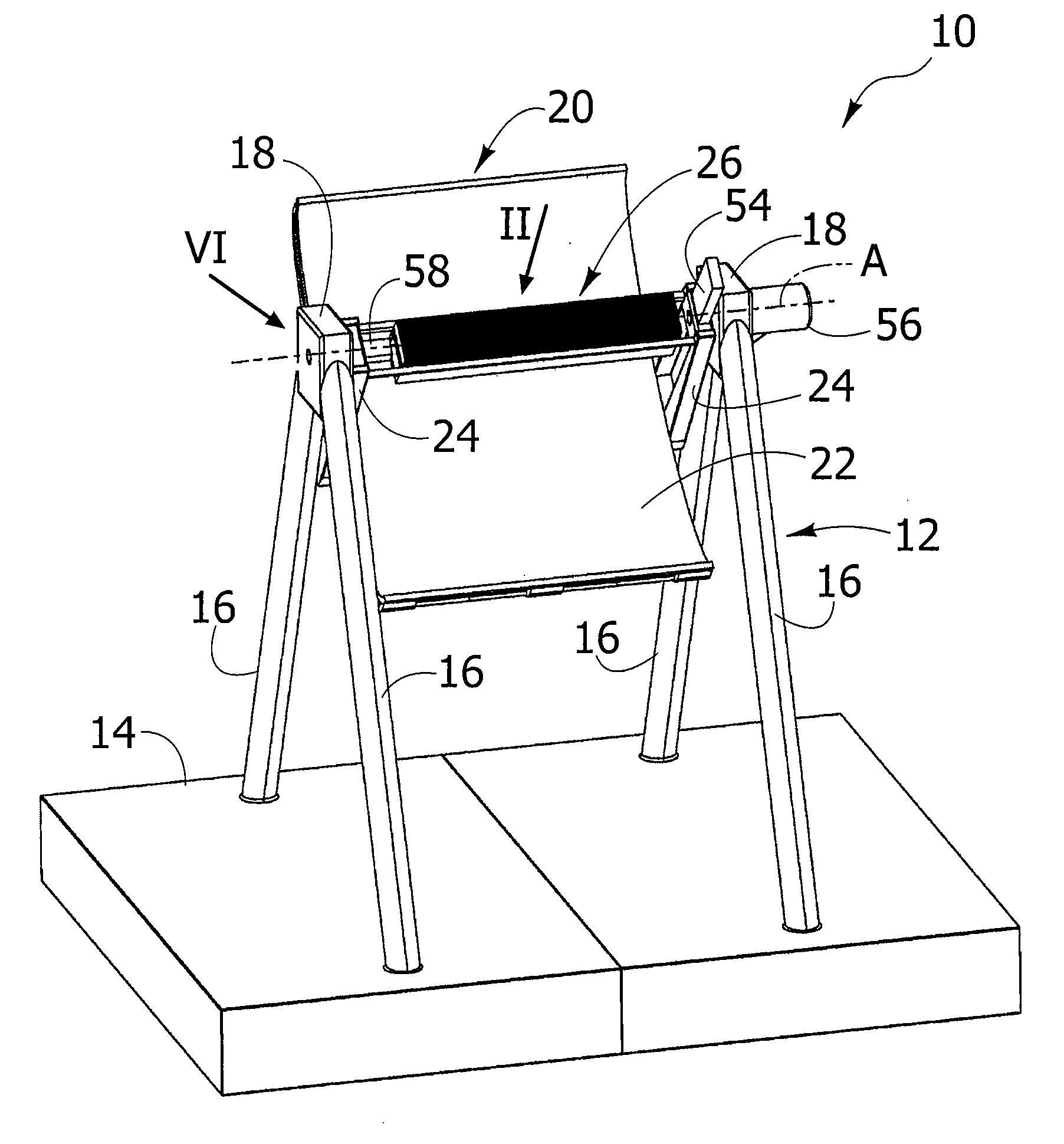
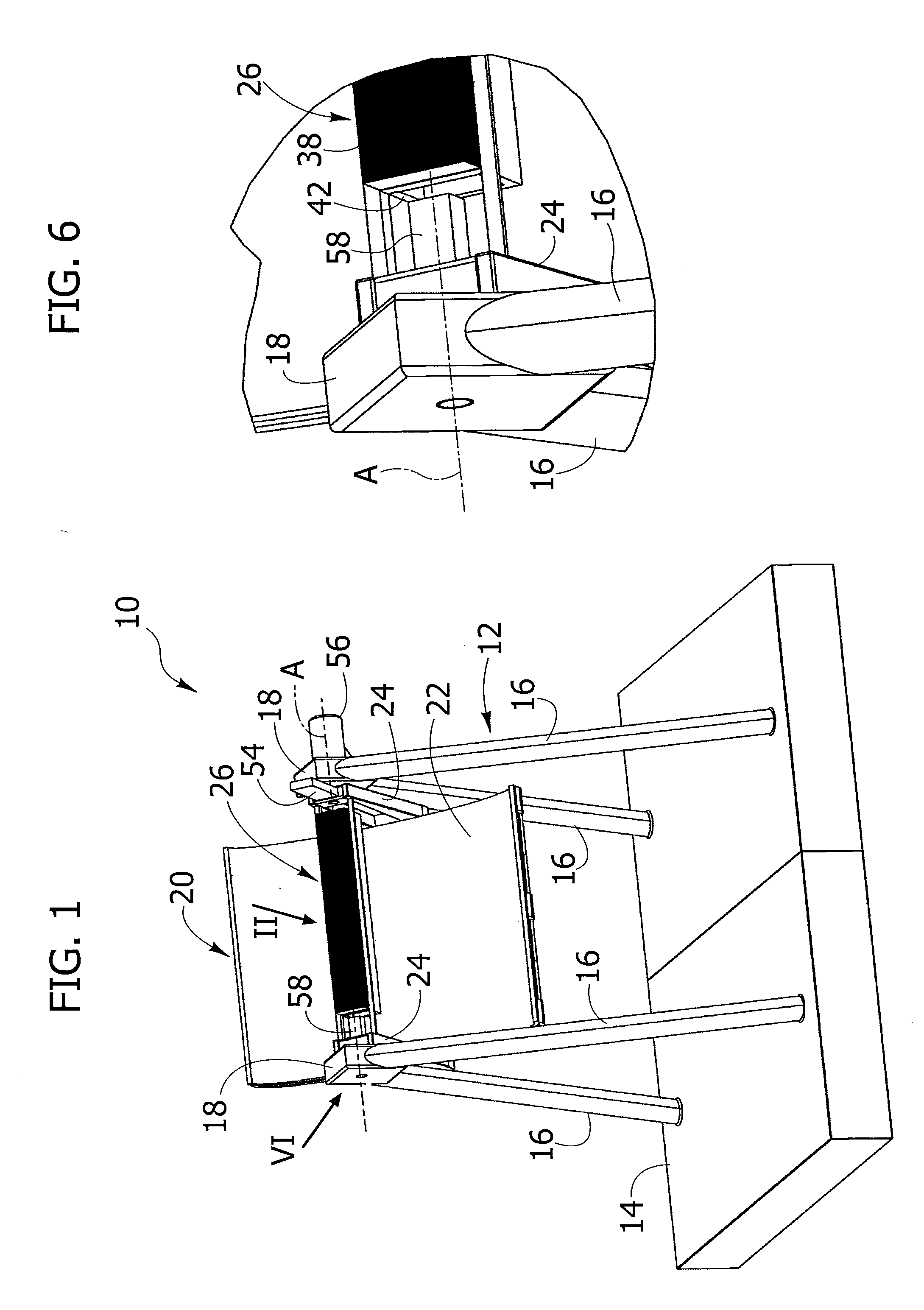
[0020]With reference to FIG. 1, designated by 10 is a high-concentration solar-energy generator, which uses a solar receiver according to the present invention. The generator 10 comprises a supporting structure 12 fixed with respect to a stationary base 14. In the example illustrated in the figures, the supporting structure 12 comprises two triangular side supports, each of which is formed by two legs 16 converging upwards. The bottom ends of the legs 16 are fixed to the base 14. The top ends of each pair of legs 16 are fixed to a respective top support 18. The shape of the supporting structure 12 that is illustrated is not, however, binding and may vary according to the applications.

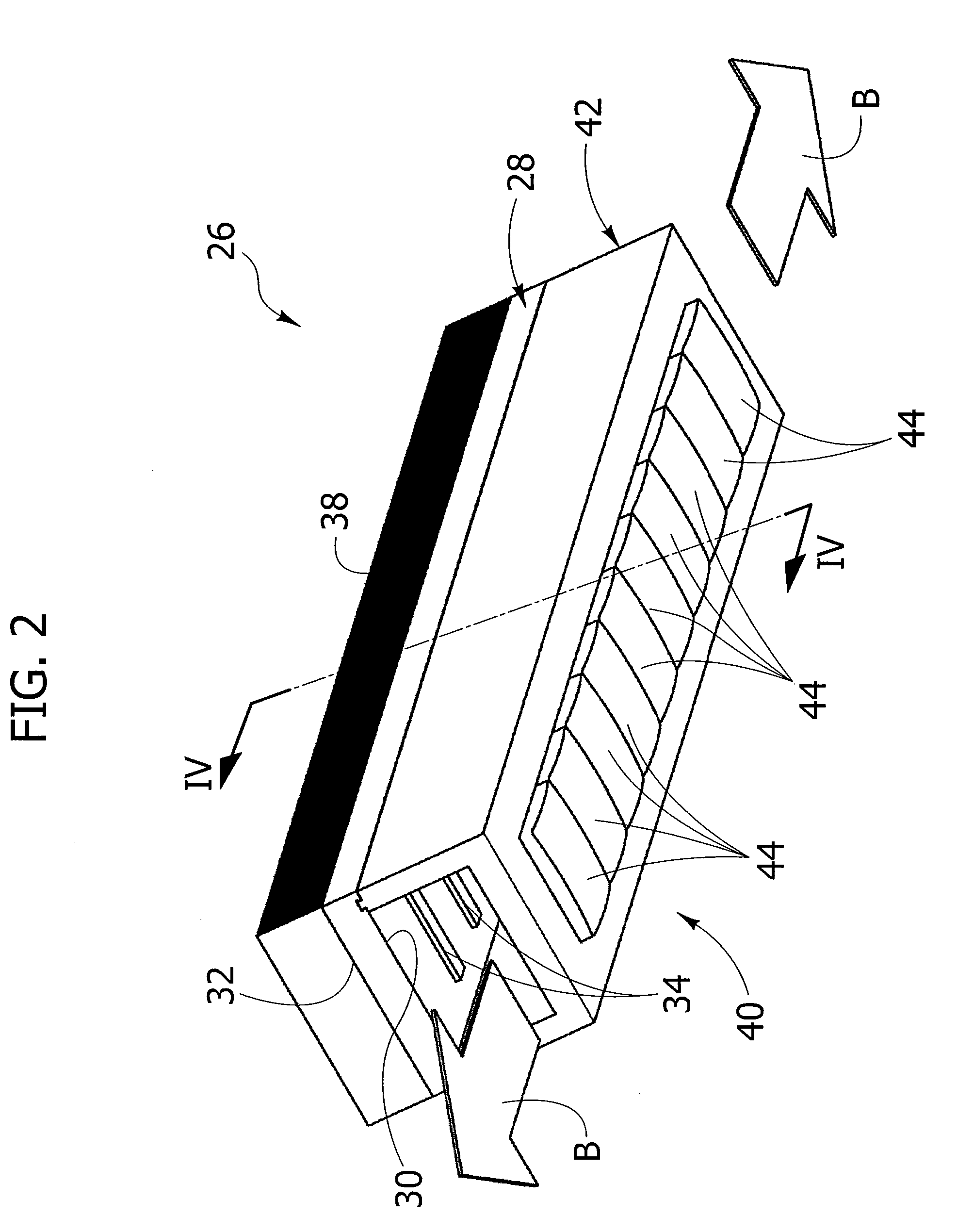
[0021]The supporting structure 12 carries a reflector 20, designed to concentrate the solar radiation on a focal line A. In the example illustrated in the figures, the reflector 20 comprises one or more mirrors with a reflecting surface 22 shaped like a parabolic cylinder. The focal axis of the reflecti...


PUM


Abstract

A solar receiver for a linear-focusing solar concentrator, comprising, a base, which is elongated in a direction parallel to a focal line and carries an array of strip-shaped targets arranged orthogonal to said focal line and set at a distance apart from one another in a direction parallel to the focal line; a focusing assembly including an array of optical elements arranged for focusing solar radiation on said strip-shaped targets, the focusing assembly being mobile with respect to the base of the photovoltaic receiver in a direction parallel to said focal line; and an azimuthal pointing device, designed to move the focusing assembly with respect to said base as a function of the position of the sun.

Description

CROSS-REFERENCE TO RELATED APPLICATIONS[0001]This application claims benefit of European Patent Application patent application serial number 09425303.6, filed Jul. 29, 2009, which is herein incorporated by reference.BACKGROUND OF THE INVENTION[0002]1. Field of the Invention[0003]The present invention relates in general to the production of energy by means of concentration of solar radiation on photovoltaic or solar receivers.[0004]In solar concentration systems it is desirable to obtain a high concentration of solar energy both for increasing the efficiency and the yield of the solar concentration system and, in the case of photovoltaic systems, for reducing the amount of photovoltaic material.[0005]2. Description of the Related Art[0006]To increase the efficiency of solar concentration systems it is necessary to carry out a pointing of the concentrators both according to the zenithal direction and according to the azimuthal direction. The document No. WO 2005 / 116534 describes a sol...

Claims


Application Information

Patent Timeline
Patent Type & Authority Applications(United States)
IPC IPC(8): F24J2/38F24S50/20F24S10/70F24S23/00
CPCF24J2/07F24J2/08F24J2/14F24J2/5266F24J2/541H01L31/0543Y02E10/52Y02E10/41Y02E10/45H01L31/0547Y02E10/47F24S20/20F24S23/30F24S23/74F24S30/20F24S30/425Y02E10/40
Inventor BALBO DI VINADIO, AIMONEPALAZZETTI, MARIO
Owner THESAN
Why Eureka
Try Eureka