Plate Heat Exchanger

a heat exchanger and plate technology, applied in the direction of heat exchanger fastening, lighting and heating apparatus, reinforcement means, etc., can solve the problems of small distance between the contact area or joining area of adjacent heat exchanger plates in the plate package, and the distance between them will be relatively short, so as to improve the strength of the joining and increase the strength of the plate package. , the effect of high strength

Active Publication Date: 2011-02-03
ALFA LAVAL CORP AB
View PDF10 Cites 16 Cited by
  • Summary
  • Abstract
  • Description
  • Claims
  • Application Information

AI Technical Summary

Benefits of technology

[0010]According to a further embodiment of the invention, the braze material has a braze volume with respect to the heat exchanger area of the plate heat exchanger, wherein the first interspaces and the second interspaces have an interspace volume with respect to the heat transfer area of the plate heat exchanger and wherein the proportion of the braze volume to the interspace volume is at least 0,05. Such a relatively large volume of braze material enhances the strength of the joining between the heat exchanger plates, and thus the strength of the plate heat exchanger.
[0011]According to a further embodiment of the invention, each heat exchanger plate defines a longitudinal centre line, wherein the heat transfer area comprises ridges and valleys arranged in such a manner that the ridges of one of the heat exchanger plates abut the valleys of an adjoining one of the heat exchanger plates to form a plurality of joining areas. Advantageously, the ridges and valleys extend along at least an extension line forming an angle α of inclination with the centre line, wherein the angle α of inclination lies in the range 20≦α≦70°. Preferably, the angle α of inclination is approximately 45°. Such an angle α of inclination provides a maximum of joining areas, and thus contributes to a high strength of the plate package and the plate heat exchanger.
[0012]According to a further embodiment of the invention, the extension line of each ridge and valley forms a positive angle α of inclination at one side of the centre line and a corresponding negative angle of inclination at the other side of the centre line, wherein the ridges and valleys form joining areas at the centre line. Such joining areas at the centre line provide a high strength in this area.

Problems solved by technology

Such a small distance between the corrugation elements means that the distance between the contact areas or joining areas between adjacent heat exchanger plates in the plate package also will be relatively short.
Consequently, a small depth results in a small distance between the joining areas, and thus in a large number of such joining areas over the heat transfer area.

Method used


Image

  • Plate Heat Exchanger
  • Plate Heat Exchanger
  • Plate Heat Exchanger

Examples


Embodiment Construction

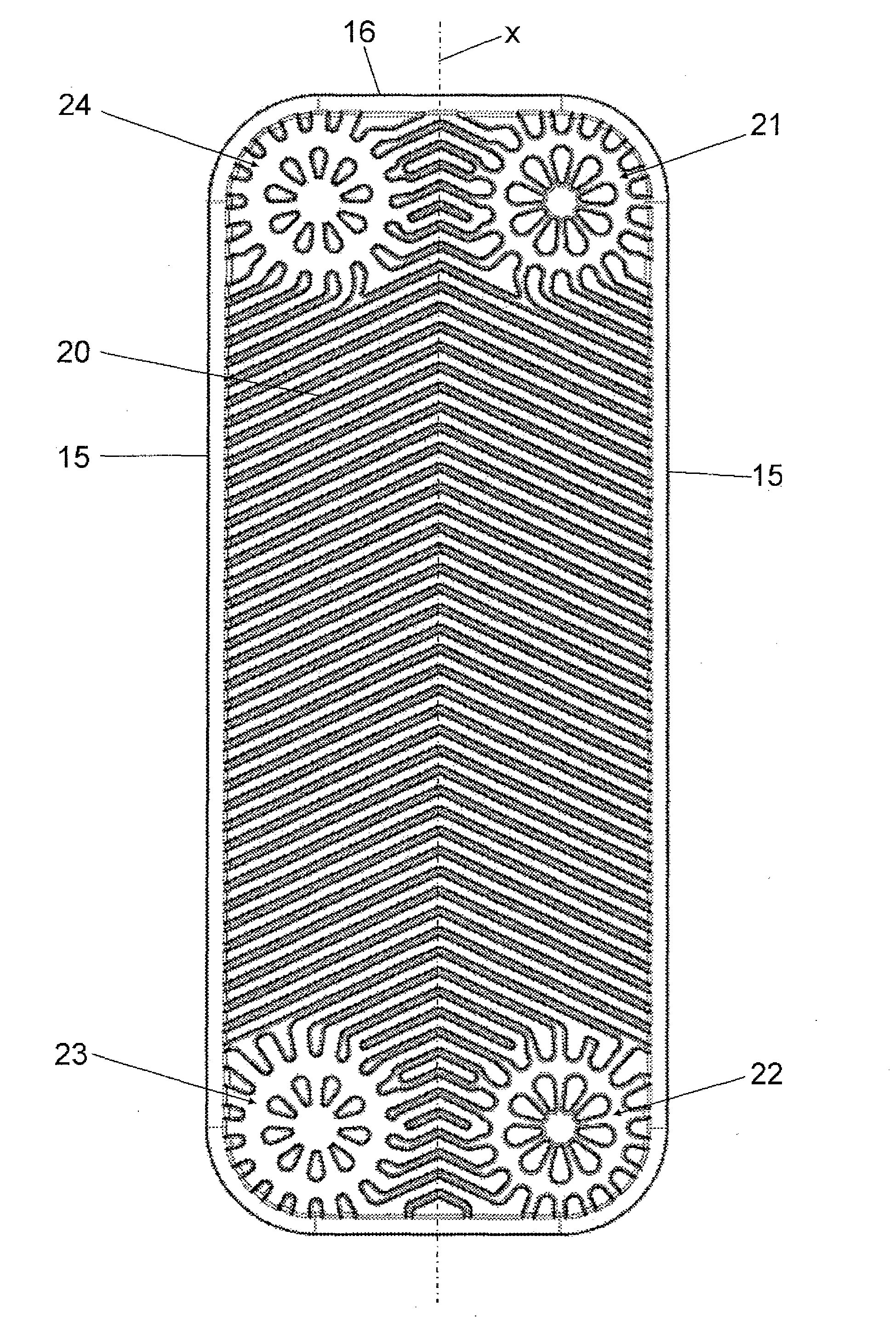
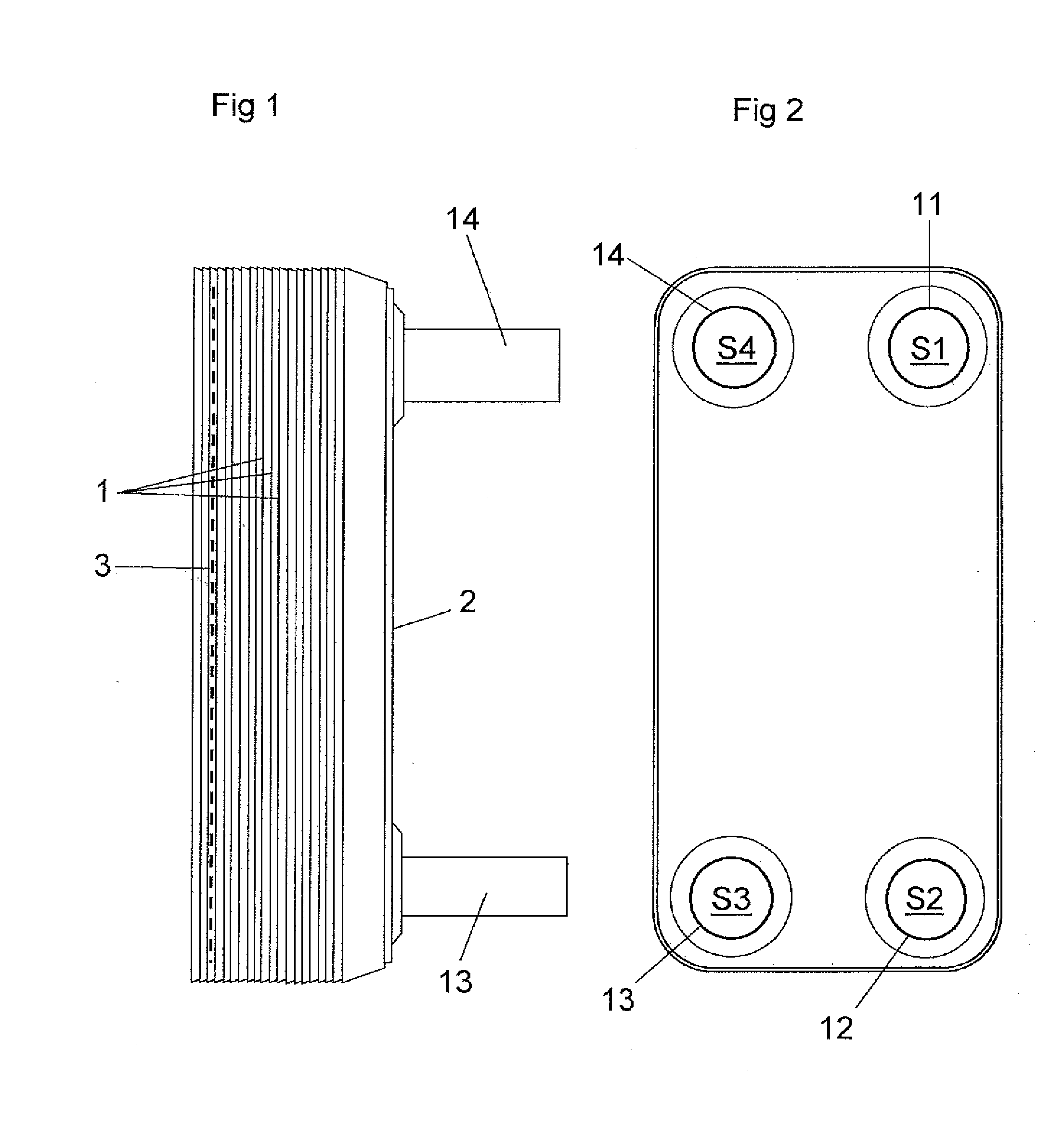
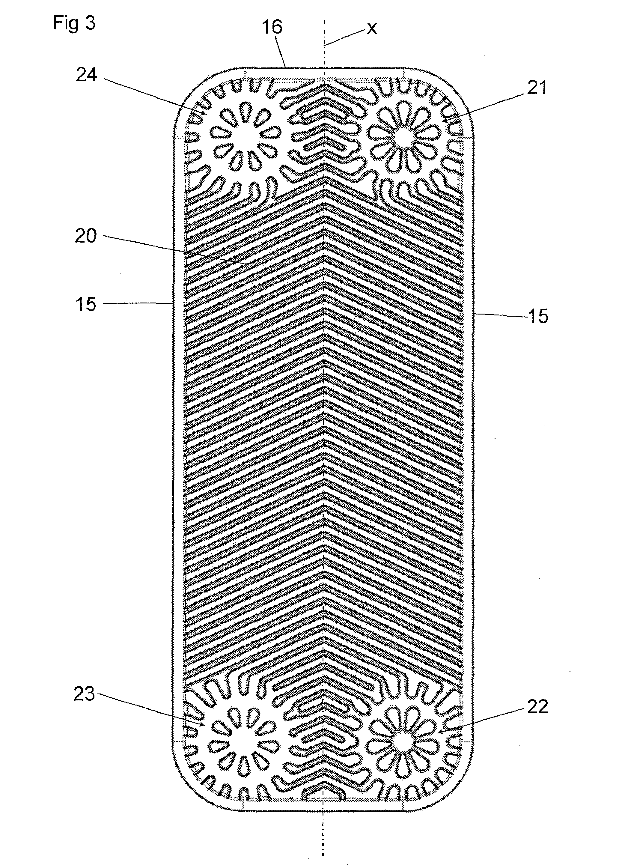
[0027]FIGS. 1 and 2 shows a plate heat exchanger comprising a plurality of heat exchanger plates 1, a first end plate 2, which is provided beside an outermost one of the heat exchanger plates 1, and a second end plate 3, which is provided beside the other opposite outermost heat exchanger plate 1.

[0028]The heat exchanger plates 1 are produced through forming of a metal sheet and provided beside each other. The first end plate 2, the second end plate 3 and the heat exchanger plates 1 are permanently joined to each other through brazing by means of a braze material to form a plate package. The plate package define or have first plate interspaces 4 for a first medium and second plate interspaces 5 for a second medium, see FIG. 6. The first and second medium may be any suitable heat transfer medium. For instance, the first and / or the second medium may be carbon dioxide.

[0029]The plate heat exchanger of the embodiments disclosed has four portholes S1, S2, S3 and S4, wherein the porthole ...


PUM


Abstract

A plate heat exchanger comprises a plurality of heat exchanger plates (1) formed of a metal sheet and permanently joined to each other by means of a braze material to form a plate package having first plate inter spaces (4) and second plate inter spaces (5). Each heat exchanger plate has a pattern forming a heat transfer area and a plurality of porthole areas. Each heat exchanger plate extends along a main extension plane (p). The areas extend, on one side of the heat exchanger plate, between a primary level (p′) at a distance from the main extension plane and a secondary level (p′) at a distance from and on an opposite side of the main extension plane. Each heat exchanger plate has a depth (d) defined by the distance between the primary level and the secondary level. The depth is equal to or less than 1.0 mm.

Description

THE FIELD OF THE INVENTION[0001]The present invention refers to a plate heat exchanger according to the preamble of claim 1.[0002]In many heat exchanger applications, it is desirable to achieve a high, or a very high, design pressure, i.e. to be able to permit a high, or a very high, pressure of one or both of the media flowing through the plate interspaces. It is also desirable to be able to permit such high pressures in plate heat exchangers of the kind defined above having permanently joined heat exchanger plates, e.g. through brazing. Such high design pressures are difficult to achieve without the provision of external strengthening components.[0003]A weak area in such plate heat exchangers is the porthole area, i.e. the area immediately around the portholes. These areas determine the design pressure in plate heat exchangers used today. However, although a certain design of the porthole area would improve the design pressure, this design would not improve the strength at another...

Claims


Application Information

Patent Timeline
Patent Type & Authority Applications(United States)
IPC IPC(8): F28F3/08
CPCF28D9/005F28F3/046F28F2225/04F28D2021/0085F28F2275/04F28D2021/0084
Inventor CHRISTENSEN, ROLFANDREASSON, FREDRIKBERMHULT, ROLFLARSSON, HAKANSVENSSON, MAGNUS
Owner ALFA LAVAL CORP AB
Why Eureka
Try Eureka