
IC package tray embedded RFID

a technology of rfid and packaging tray, which is applied in the direction of containers, burglar alarm mechanical actuation, instruments, etc., can solve the problems that the aging of the tray material cannot be found through inspection and measurement processes, and achieve the effect of improving the accuracy and convenience of tracking the usage of the tray, and determining quickly and conveniently

Active Publication Date: 2011-02-03
MACRONIX INT CO LTD
View PDF9 Cites 3 Cited by
  • Summary
  • Abstract
  • Description
  • Claims
  • Application Information

AI Technical Summary

Benefits of technology

[0013]The counter value information present on the device improves the accuracy and convenience of tracking usage of the tray. A decision about whether to permit the use of the carrier tray in subsequent manufacturing processes can be determined quickly and conveniently by merely interrogating the device attached thereto, without incurring the cost and delay of extensive quality control measures or the detailed usage tracking of the tray in a distributed manufacturing facility arrangement.
[0014]Storing the counter value has a number of advantages over simply storing large data files indicating the detailed usage of the tray. For example, instead of having to read and update large data structures stored on the device or in a remote database, by using the counter value to track the usage of the tray a relatively small amount of data is stored, modified, and transmitted.

Problems solved by technology

Some problems caused by the aging of the tray material cannot be found by inspection and measurement processes.

Method used


Image

  • IC package tray embedded RFID
  • IC package tray embedded RFID
  • IC package tray embedded RFID

Examples


Embodiment Construction

[0028]A detailed description of embodiments of the present invention is provided with reference to FIGS. 1 to 9.

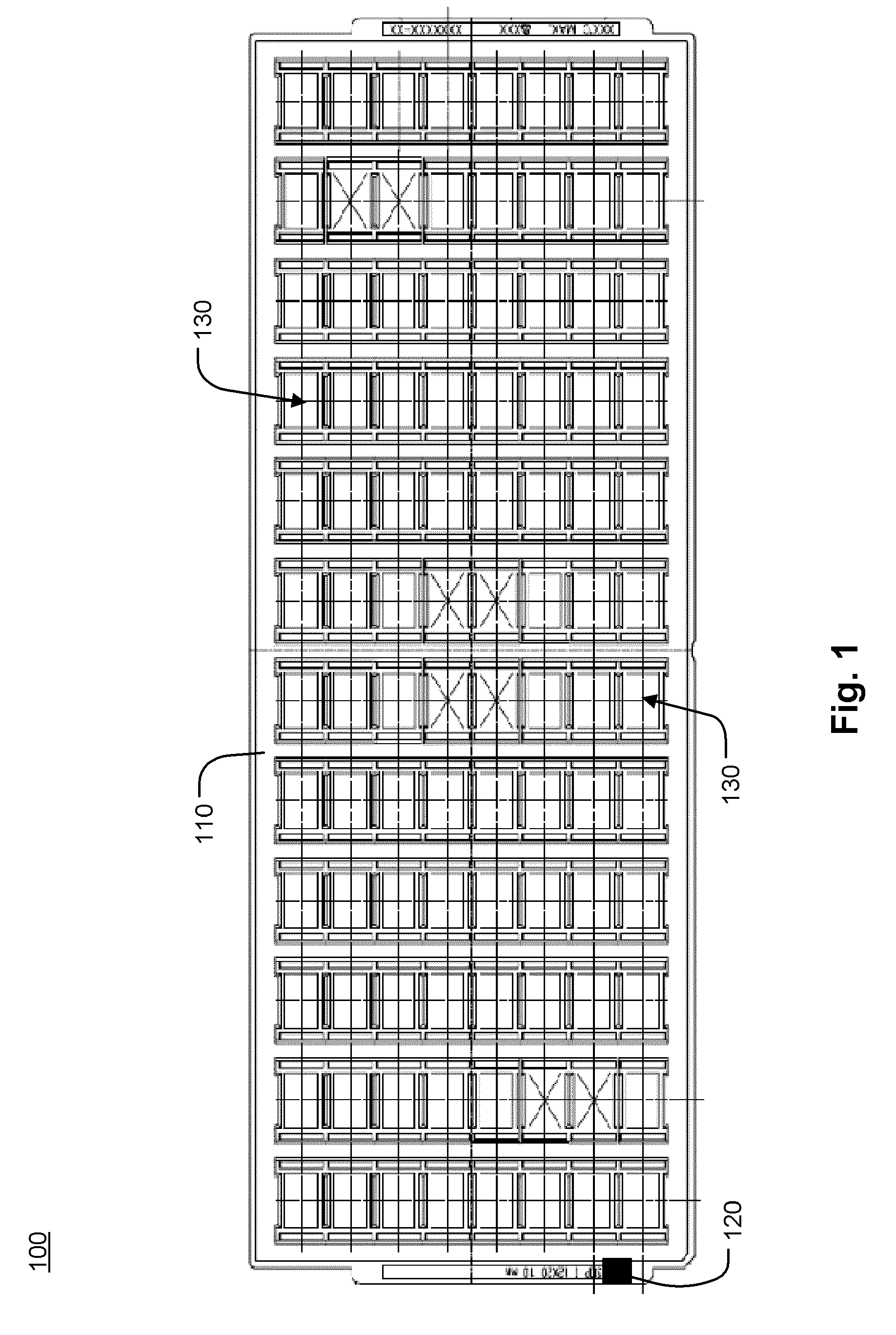
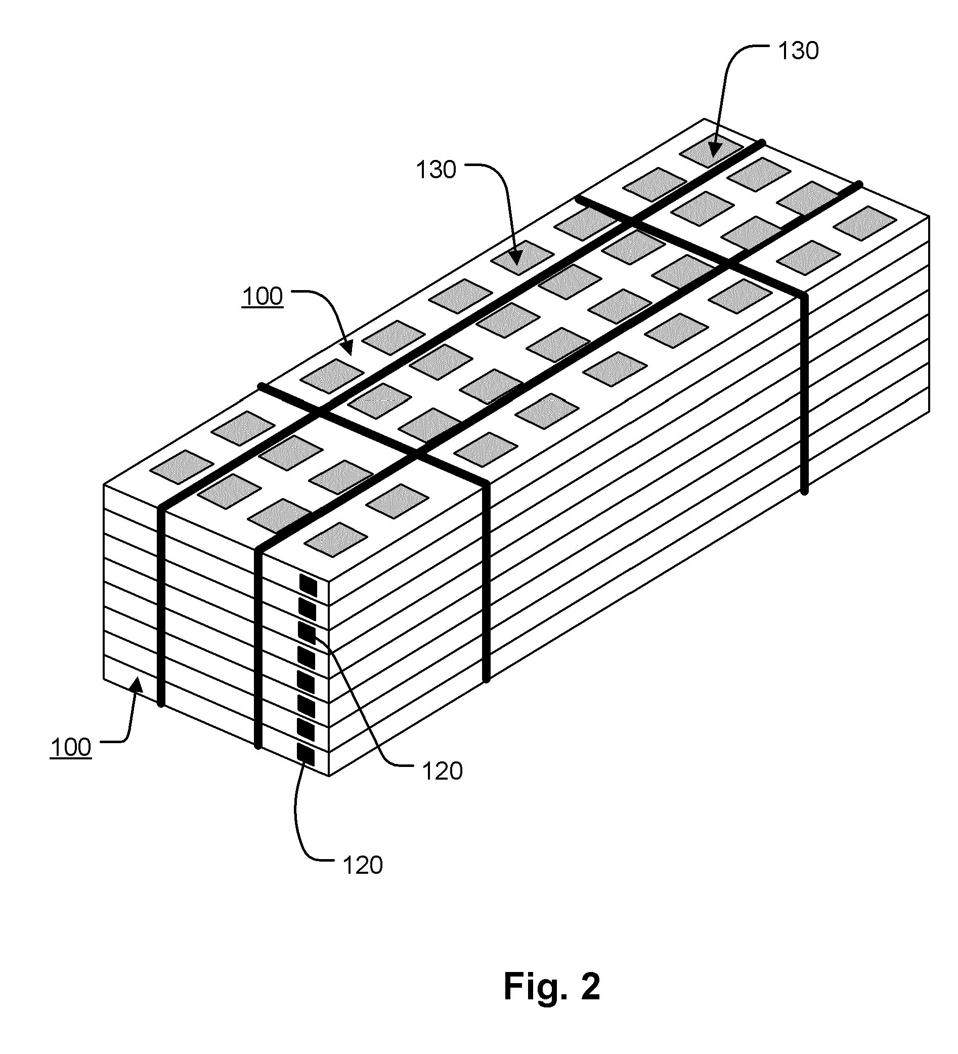
[0029]FIG. 1 is a plan view illustration of an embodiment of a carrier tray 100 including a container 110 used to hold electrical components such as integrated circuits during manufacturing, and device 120 attached to or embedded within the material of the container 110. In the illustrated example, the device 120 is a radio frequency identification (RFID) device and includes software and circuitry to permanently store an identification code usable by an RFID reader or writer to identity the corresponding container 110. Alternatively, the device 120 is not an RFID device and other techniques for identifying the corresponding container 110 may be used. As described in more detail below, the RFID device 120 is used to track the number of times the carrier tray 100 has been passed into and out of process chambers.

[0030]The term “process chamber” as used herein broadly refers t...


PUM


Abstract

A carrier tray as described herein includes a container having pockets for holding electrical components such as integrated circuits during manufacturing, and a device coupled to the container for tracking usage of the carrier tray into and out of process chambers used for performing particular processes on the electrical components carried therein. Stations and methods of using the carrier tray are also described herein.

Description

BACKGROUND OF THE INVENTION[0001]1. Field of the Invention[0002]The present invention relates generally to a carrier tray used during manufacturing of electrical components, and more particularly to systems and methods of using the carrier tray which allow for reuse of the carrier tray a large number of times.[0003]2. Description of Related Art[0004]In the manufacture of electrical components such as semiconductor integrated circuit devices, the components are placed in carrier trays that house and protect the components from damage during various processing, production, testing and assembly station operations. The carrier trays can also orient the electrical components to ensure proper placement and alignment during testing and insertion onto a printed circuit board. The various station operations are typically carried out at geographically dispersed locations, which necessitate shipment of the components in the carrier trays.[0005]The carrier trays experience the same environment ...

Claims


Application Information

Patent Timeline
IPC IPC(8): B65D85/86B65D1/36G06F17/00H04Q5/22
CPCH01L21/67333H01L21/67294
Inventor LEE, JUI-CHUNGKO, CHUN-MINGWANG, LAN-BEN
Owner MACRONIX INT CO LTD
Learn More