[0006]The secondary part preferably has at least one permanent
magnet. It is particularly preferable to use a plurality of permanent magnets, which are arranged alternately. In conjunction with teeth on a
stator, this makes it possible to form cogging locations with high cogging forces at periodically recurring positions. Embodiments are particularly preferable in which at least one permanent
magnet is additionally provided on the primary part, in order to further increase the cogging force. A short-circuiting circuit, which can be activated when no current is flowing, offers an additional
brake against inadvertent movement of the machine. A short-circuiting circuit such as this is provided in order to short-circuit an
electromagnet in the machine, which is preferably arranged on the primary part. Although the short-circuiting braking torque or the short-circuiting braking force acts only during movement along the degree of freedom of the machine, this makes it possible to cope with force or torque surges so as to largely prevent temporary rotary movement or translational movement. In this case, in the case of a rotating machine, a movement degree of freedom means the rotation of the shaft of the machine and, in the case of a
linear machine, it means the linear movement of the translator with respect to the
stator.
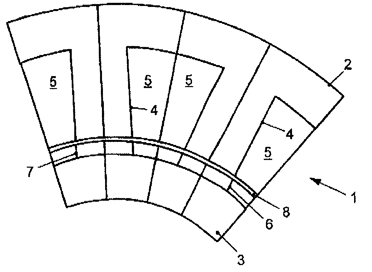
[0008]The width of one tooth at its head, that is to say the tooth width, of at least one tooth on the primary part is advantageously at least 20%, more preferably at least 30%, of the slot
pitch of the primary part. In this case, in the case of a rotating machine, one angle width of the tooth preferably corresponds to the tooth width at the air gap between the primary part and the secondary part. It is furthermore preferable for the tooth width of at least one tooth on the primary part to correspond at most to 80% of the slot
pitch of the primary part, more preferably at most 65%, and even more preferably at most 55%. Furthermore, it is preferable for one tooth width of at least one tooth on the primary part to correspond to at least 80%, more preferably 90% or 95%, of one
magnet width of the primary part. In this case, the magnet width is the width of the coil winding or of the coil windings between two teeth. The tooth width of at least one tooth on the primary part preferably corresponds to at most 120%, more preferably 110% or 105%, of one magnet width in the primary part. It should be noted that, in the case of all the relative details in this
paragraph which relate to a tooth, this in each case expressly discloses the idea that at least half of all the teeth on the primary part or all the teeth on the primary part are correspondingly designed. In general, the stated features offer the
advantage that the cogging force is increased.
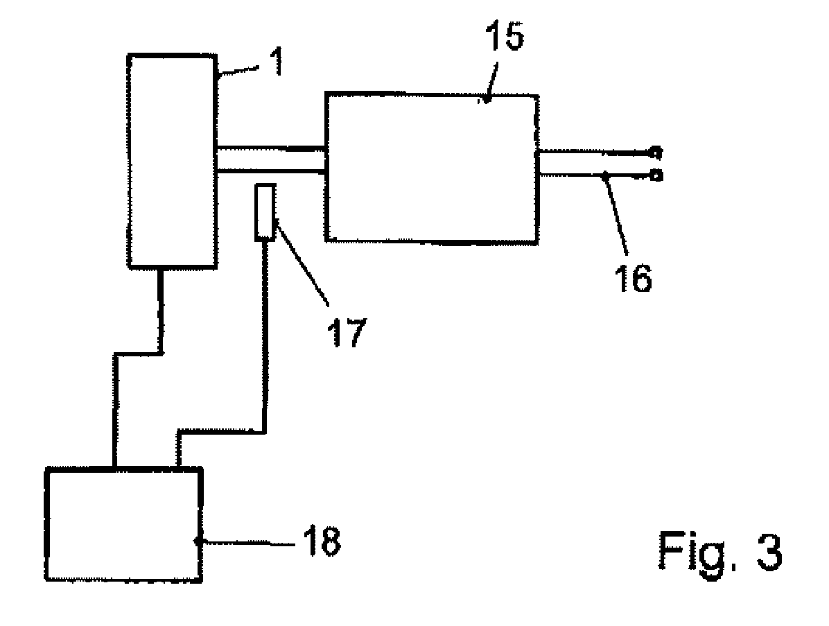
[0009]The machine advantageously has at least one
control unit which is designed to pass current through an
electromagnet in the machine such that the cogging force is reduced. Deliberately passing current through at least one
electromagnet, or preferably at least half the electromagnets, in the primary part makes it possible to ensure that the cogging force is reduced. The current flow is preferably varied periodically. The current required for compensation is in this case calculated from the contour integral of the
field strength divided by the number of turns. The current is preferably fed in in antiphase. This results in a maximum reduction in the cogging force. The
period duration is preferably chosen as a function of the rotation speed of the machine. The amplitude profile of the current is expediently determined as a function of a
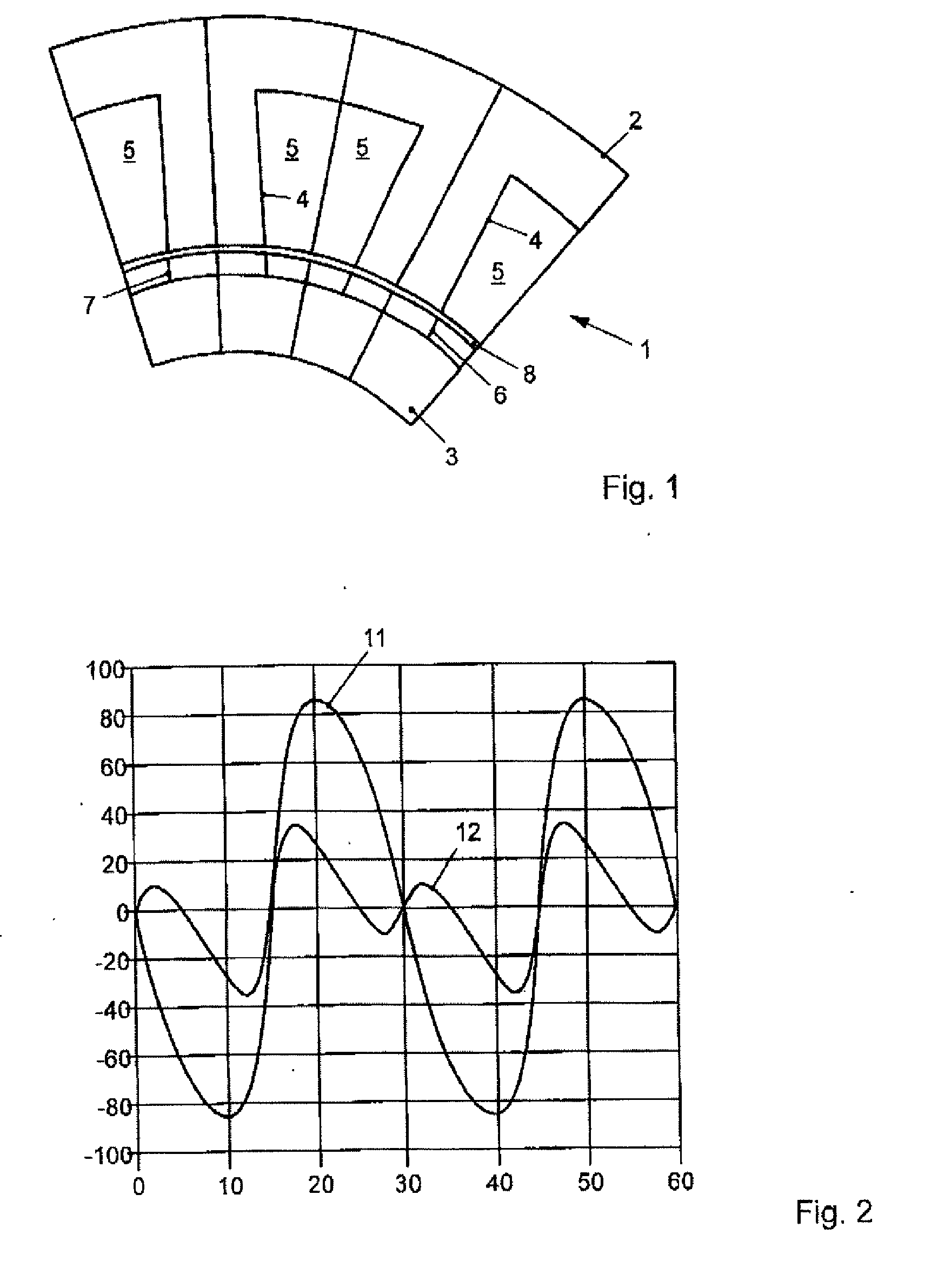
force profile during movement when no current is flowing. In this case, the shaft, the translator or the rotor, or in general the secondary part, is moved, and the
force profile is measured when no current is flowing. It is likewise possible to determine the
force profile when no current is flowing by calculation. This force profile is evaluated in order to apply the current, appropriately in antiphase, to the coil or to the coil ends. The current advantageously flows so as to at least largely compensate for the cogging force. In this case, largely means compensation of at least 50%, more preferably 70% or 80%. This offers the
advantage that the machine can be run sufficiently smoothly, despite the high cogging force. The machine preferably has a
control unit which is designed to allow one of the preferred current flows mentioned above through the electromagnet.

