
Vibrating body and vibration wave actuator

a technology of vibration wave actuator and vibration body, which is applied in the direction of mechanical vibration separation, piezoelectric/electrostrictive/magnetostrictive devices, piezoelectric/electrostrictive/magnetostriction machines, etc., can solve the problems of increasing reducing the efficiency of the small-type vibration wave actuator, and reducing the attenuation of the vibrating body. , to achieve the effect o

Inactive Publication Date: 2011-02-03
CANON KK
View PDF21 Cites 16 Cited by
  • Summary
  • Abstract
  • Description
  • Claims
  • Application Information

AI Technical Summary

Benefits of technology

The present invention provides a vibrating body and a vibration wave actuator that can suppress vibration attenuation while reducing size and cost. This improves vibration efficiency and ensures stable output of vibration energy. The vibrating body includes a piezoelectric element, a ceramic substrate, and a ceramic layer, while the vibration wave actuator includes the vibrating body as a driving power source.

Problems solved by technology

However, the adhesive made of the resin is relatively soft, and hence vibration attenuation due to the adhesive as the vibrating body is large.
In particular, as the vibrating body becomes smaller in size, the effect of vibration attenuation of the vibrating body becomes larger, which is a main cause of decreasing efficiency of the small type vibration wave actuator.
In addition, in a manufacturing method for the conventional laminated piezoelectric element, the amount of capital investment for a manufacturing apparatus relating to molding of the green sheet made of the piezoelectric material powder, laminating press, mechanical working, and the like is also large, which contributes to an increase of manufacturing cost.
However, between the electrode layer made of a noble metal and the ceramic substrate being in direct contact with the electrode layer, there are few chemical reactions, and hence the joining strength decreases to a large degree.
Therefore, there arises a case where stable vibration energy cannot be output.

Method used


Image

  • Vibrating body and vibration wave actuator
  • Vibrating body and vibration wave actuator
  • Vibrating body and vibration wave actuator

Examples


first embodiment

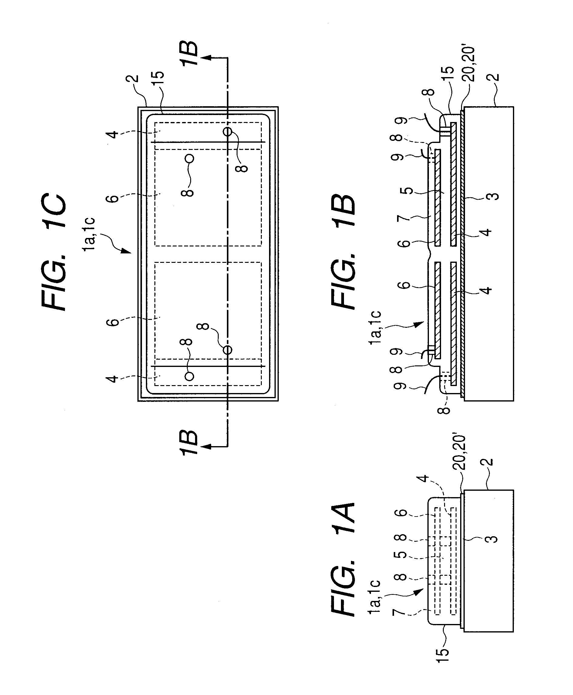
[0036]Referring to FIGS. 1A to 1C, a structure of a vibrating body according to a first embodiment of the present invention is described.

[0037]Note that, FIG. 1B illustrates a section of a portion illustrated by the dashed line indicated by the arrow of FIG. 1C. A vibrating body 1a illustrated in FIGS. 1A to 1C is envisaged to be applied to a linear driving vibration wave actuator.

[0038]The vibrating body 1a includes a plate-like ceramic substrate 2 and a piezoelectric element 15. Between the plate-like ceramic substrate 2 and the piezoelectric element 15, a ceramic layer 20 is provided.

[0039]The ceramic substrate 2 and the piezoelectric element 15 are fixed to be integrated to each other through intermediation of the ceramic layer 20 by co-firing as described below.

[0040]That is, the piezoelectric element 15 functioning as a vibration energy generating source and the ceramic substrate 2 functioning as a vibrating plate for accumulating the generated vibration energy are fixed to be...

second embodiment

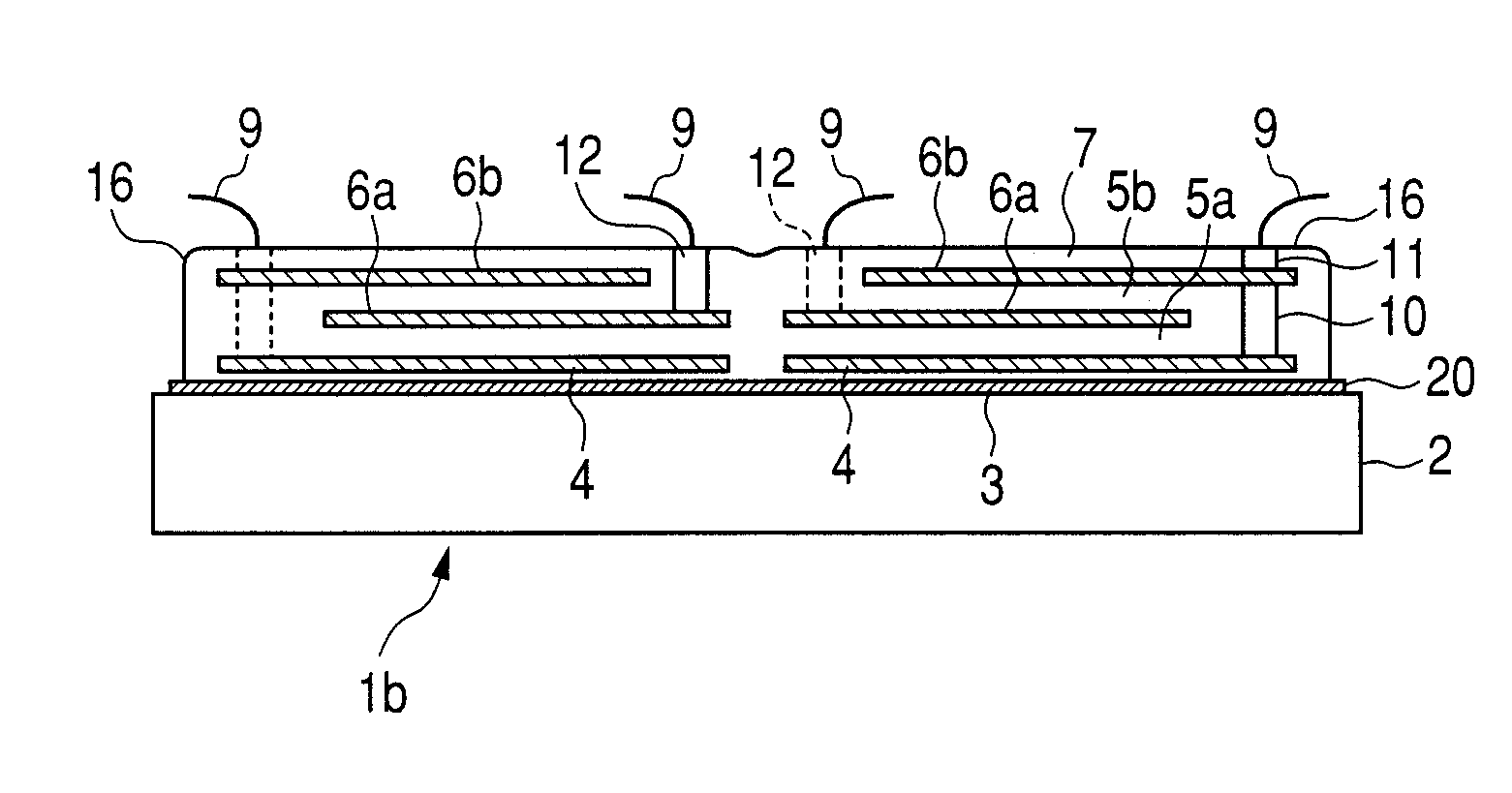
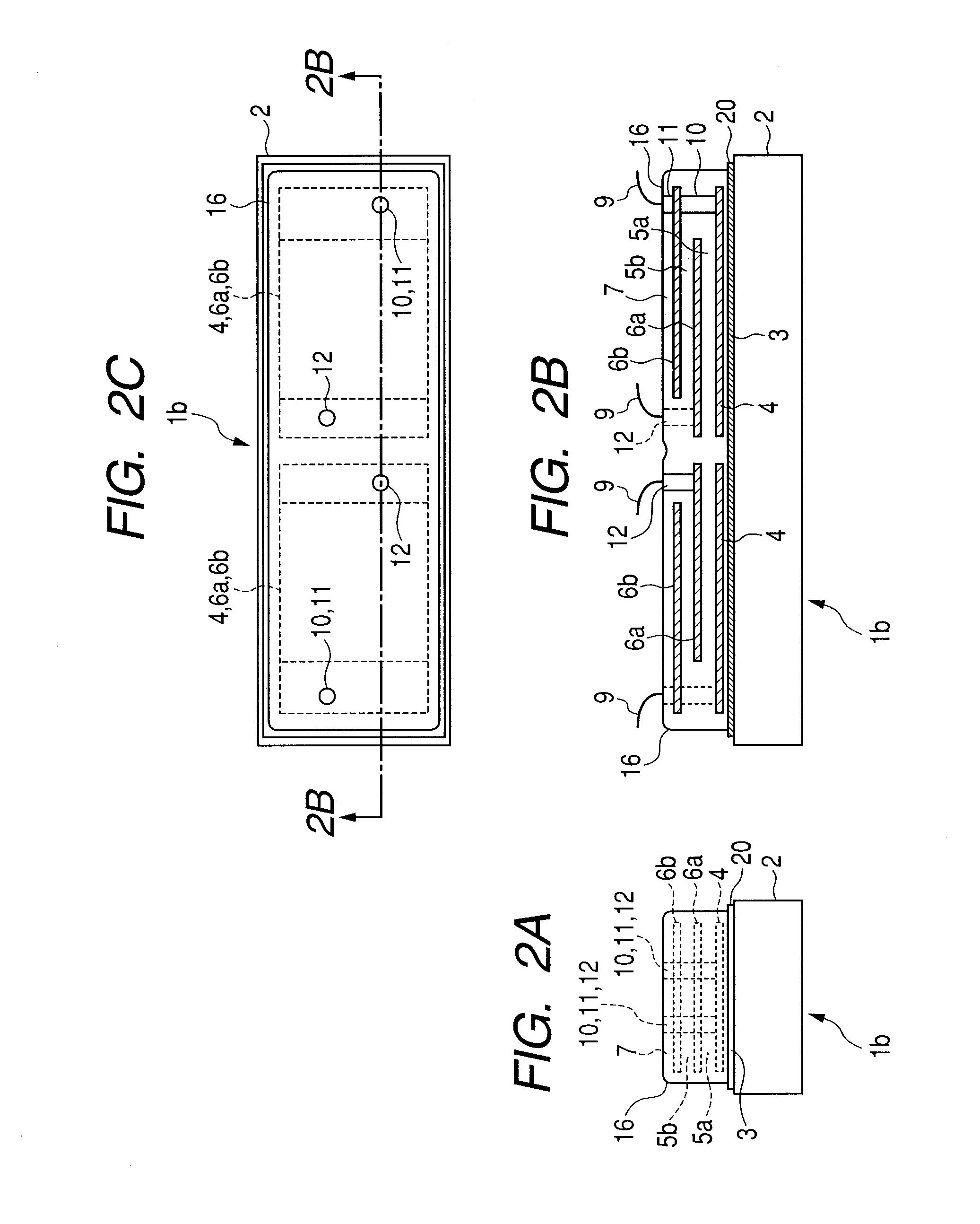
[0108]Referring to FIGS. 2A to 2C, a structure of a vibrating body according to a second embodiment of the present invention is described.

[0109]Note that, FIG. 2B illustrates a section of a portion illustrated by the dashed line indicated by the arrow of FIG. 2C.

[0110]In the first embodiment described above, one piezoelectric layer is sandwiched between the electrode layers. Meanwhile, in the second embodiment, two piezoelectric layers are respectively sandwiched between the electrode layers.

[0111]That is, in the second embodiment, a laminated piezoelectric element 16 is provided through adding another piezoelectric layer and another electrode layer with respect to the first embodiment.

[0112]In other words, in the second embodiment, two piezoelectric layers as piezoelectric active portions are used, and hence lower voltage operation is achieved in comparison with the first embodiment in which the one piezoelectric layer is used.

[0113]Note that, three or more piezoelectric layers as ...

third embodiment

[0132]Referring to FIGS. 1A to 1C, a structure of a vibrating body according to a third embodiment of the present invention is described. The third embodiment is different from the first embodiment in that the ceramic layer 20 of the first embodiment is substituted by a ceramic layer 20′ including glass powder.

[0133]FIG. 1B illustrates a section taken along the dashed line indicated by the arrow of FIG. 1C. A vibrating body 1c illustrated in FIGS. 1A to 1C is envisaged to be applied to a linear-driving vibration wave actuator.

[0134]The vibrating body 1c includes a plate-like ceramic substrate 2 and a piezoelectric element 15. Between the plate-like ceramic substrate 2 and the piezoelectric element 15, the ceramic layer 20′ is provided.

[0135]The ceramic substrate 2 and the piezoelectric element 15 are fixed (joined) to be integrated to each other through intermediation of the ceramic layer 20′ by co-firing as described below.

[0136]That is, the piezoelectric element 15 functioning as ...


PUM

PropertyMeasurementUnit
thicknessaaaaaaaaaa
thicknessaaaaaaaaaa
thicknessaaaaaaaaaa

Abstract

Provided are a vibrating body and a vibration wave actuator, which can suppress vibration attenuation along with a reduction in size with an inexpensive structure, to thereby improve vibration efficiency, and can output stable vibration energy. A vibrating body includes: a piezoelectric element including a piezoelectric layer and an electrode layer; a ceramic substrate to which the piezoelectric element is fixed; and a ceramic layer including the same main component as a main component of the ceramic substrate, which is provided between the piezoelectric element and the ceramic substrate, and the piezoelectric element is fixed to the ceramic substrate through intermediation of the ceramic layer.

Description

BACKGROUND OF THE INVENTION[0001]1. Field of the Invention[0002]The present invention relates to a vibrating body and a vibration wave actuator, and more particularly, to a vibrating body including a piezoelectric element fixed to a ceramic substrate and a vibration wave actuator using the vibrating body.[0003]2. Description of the Related Art[0004]Conventionally, in a vibration wave actuator, a piezoelectric element is generally used as a vibration source for a vibrating body.[0005]As the piezoelectric element, a laminated piezoelectric element is used (U.S. Pat. No. 7,109,639). The laminated piezoelectric element is obtained through laminating a large number of piezoelectric layers on each other and integrally molding the laminated piezoelectric layers before firing.[0006]The laminated piezoelectric element has an advantage of obtaining, due to multi-layers thereof, larger deformation (strain) and larger force at low applied voltage as compared to a single plate-like piezoelectric...

Claims


Application Information

Patent Timeline
Patent Type & Authority Applications(United States)
IPC IPC(8): H02N2/04B06B1/06H01L41/083H01L41/187H01L41/22H01L41/257H01L41/293H01L41/312H02N2/00
CPCH01L41/0906H01L41/314H01L41/1876H02N2/0015H02N2/026H10N30/053H10N30/8554H10N30/074H10N30/708H10N30/202
Inventor MARUYAMA, YUTAKA
Owner CANON KK
Learn More