
Method and apparatus for authenticating RFID tags

a technology of radiofrequency identification and authentication method, applied in the field of radiofrequency identification system, can solve the problems of insufficient on-tag storage capacity to accommodate the continuously increasing data payload, complex distributed rfid database, and difficult to understand, so as to avoid unnecessary proliferation of numbers

Active Publication Date: 2011-02-03
RFMICRON
View PDF13 Cites 64 Cited by
  • Summary
  • Abstract
  • Description
  • Claims
  • Application Information

AI Technical Summary

Benefits of technology

[0034]In the drawings, similar elements will be similarly numbered whenever possible. However, this practice is simply for convenience of reference and to avoid unnece

Problems solved by technology

Furthermore, it is of no relevance in such systems which specific voltage levels are selected to represent each of the logic states.
One such disadvantage is that smart tags tend to be relatively expensive and complex, and yet, in general, still have insufficient on-tag storage capacity to accommodate the continuously-increasing data payload.
Distributed RFID databases are typically complex, difficult to understand, and time-consuming to maintain.
Further, sensitive data is difficult to distribute reliably and difficult to maintain securely at all locations where the data may be stored.
Yet another disadvantage is in the area of security.
Privacy issues include the case of unauthorized readers harvesting information from valid tags.
Thus, without proper security, clandestine scanning of information is a plausible threat.
This threat becomes particularly sensitive when personal or proprietary information is included with the RFID tag id, or when the RFID tag id can be readily associated with that information.
Authentication issues can arise when a reader harvests information from counterfeit tags.
In general, RFID tags are vulnerable to copy and counterfeit techniques because scanning and replicating tags and tag ids requires relatively little money or expertise.
However, many such techniques add complexity and cost to the RFID tags.
As a result of these and related problems, RFID technology adoption has been far slower than originally anticipated and desired.

Method used


Image

  • Method and apparatus for authenticating RFID tags
  • Method and apparatus for authenticating RFID tags
  • Method and apparatus for authenticating RFID tags

Examples


Embodiment Construction

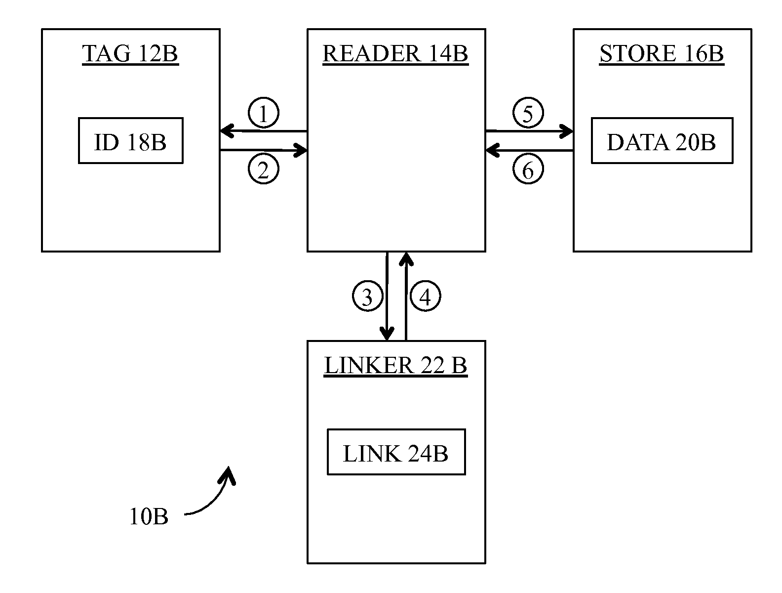
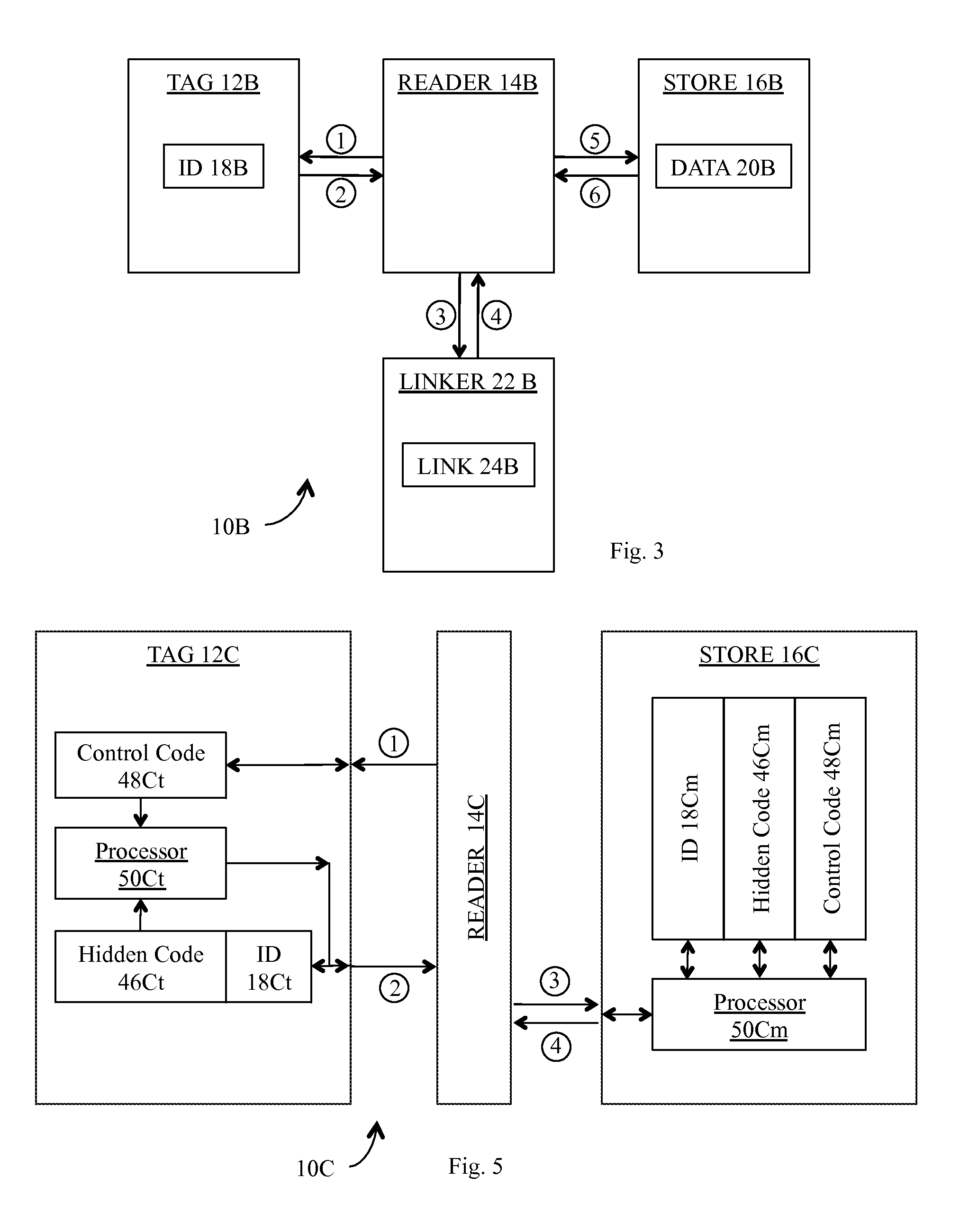
[0035]In accordance with the preferred embodiment of our invention as shown in FIG. 3, our RFID system 10B includes tag 12B, reader 14B, store 16B, and a linker 22B. In general, reader 14B is adapted to interrogate tag 12B [illustrated in FIG. 3 as transaction 1], and to receive ID 18B provided by tag 12B [transaction 2] in response to that interrogation. Reader 14B is further adapted to selectively provide ID 18B to linker 22B [transaction 3], and to receive a link 24B from linker 22B [transaction 4]. Finally, reader 14B is adapted to selectively provide the link 24B to store 16B [transaction 5], and to receive a data object 20B from store 16B [transaction 6].

[0036]As shown in FIG. 4, our preferred method 26 for linking tag 12B to a data object 20B comprises the following steps:

[0037]Step 1: we store a unique ID 18B in tag 12B (step 28).

[0038]Step 2: we store links 24B, each associated with a selected unique ID 18B, in linker 22B (step 30).

[0039]Step 3: we store data objects 20B, e...


PUM


Abstract

In an RFID system, a method and apparatus for linking an RFID tag to an associated object. The system includes a relatively simple tag, a reader, a linker, and a store. The reader interrogates the tag for an ID and selectively provides the ID to the linker. The linker, in turn, uses the ID to provide back to the reader an associated Uniform Resource Identifier (“URI”). The reader then forwards the URI to the store. In response, the store returns to the reader the object associated with the ID via the URI. The disclosed method and apparatus provide more efficient and secure tag authentication.

Description

CROSS-REFERENCE TO RELATED APPLICATIONS[0001]This application claims priority to the U.S. Provisional Patent Application Ser. No. 61 / 273,227 (“Parent Provisional”), filed 1 Aug. 2009. The foregoing Parent Provisional is hereby incorporated by reference in its entirety as if fully set forth herein. The subject matter of this application is related to U.S. application Ser. No. ______ (Attorney Docket No. JRF004) (“Related Application”), filed simultaneously herewith.BACKGROUND OF THE INVENTION[0002]1. Field of the Invention[0003]Our invention relates generally to radio-frequency identification (“RFID”) systems and, in particular, to a method and apparatus for linking an RFID tag to an associated object while addressing issues of privacy and authentication.[0004]2. Description of the Related Art[0005]In general, in the descriptions that follow, we will italicize the first occurrence of each special term of art which should be familiar to those skilled in the art of radio frequency (“RF...

Claims


Application Information

Patent Timeline
IPC IPC(8): G05B19/00
CPCG05B2219/31304H04L63/0853H04L63/0492Y02P90/02G06Q20/382G06Q20/3827G06Q20/388
Inventor ROKHSAZ, SHAHRIARDE ANGEL, EDWIN
Owner RFMICRON
Learn More