
Antenna Diversity For Wireless Tracking System And Method

a wireless tracking and diversity technology, applied in the field of wireless tracking systems and objects wireless tracking, can solve the problems of inability to provide accurate location estimates for in-building environments, inability to provide single characteristics accurate location estimates, and sometimes erroneous assumption, etc., to improve the accuracy of received signal strength indications

Inactive Publication Date: 2011-02-03
AWAREPOINT CORPORATION
View PDF49 Cites 22 Cited by
  • Summary
  • Abstract
  • Description
  • Claims
  • Application Information

AI Technical Summary

Benefits of technology

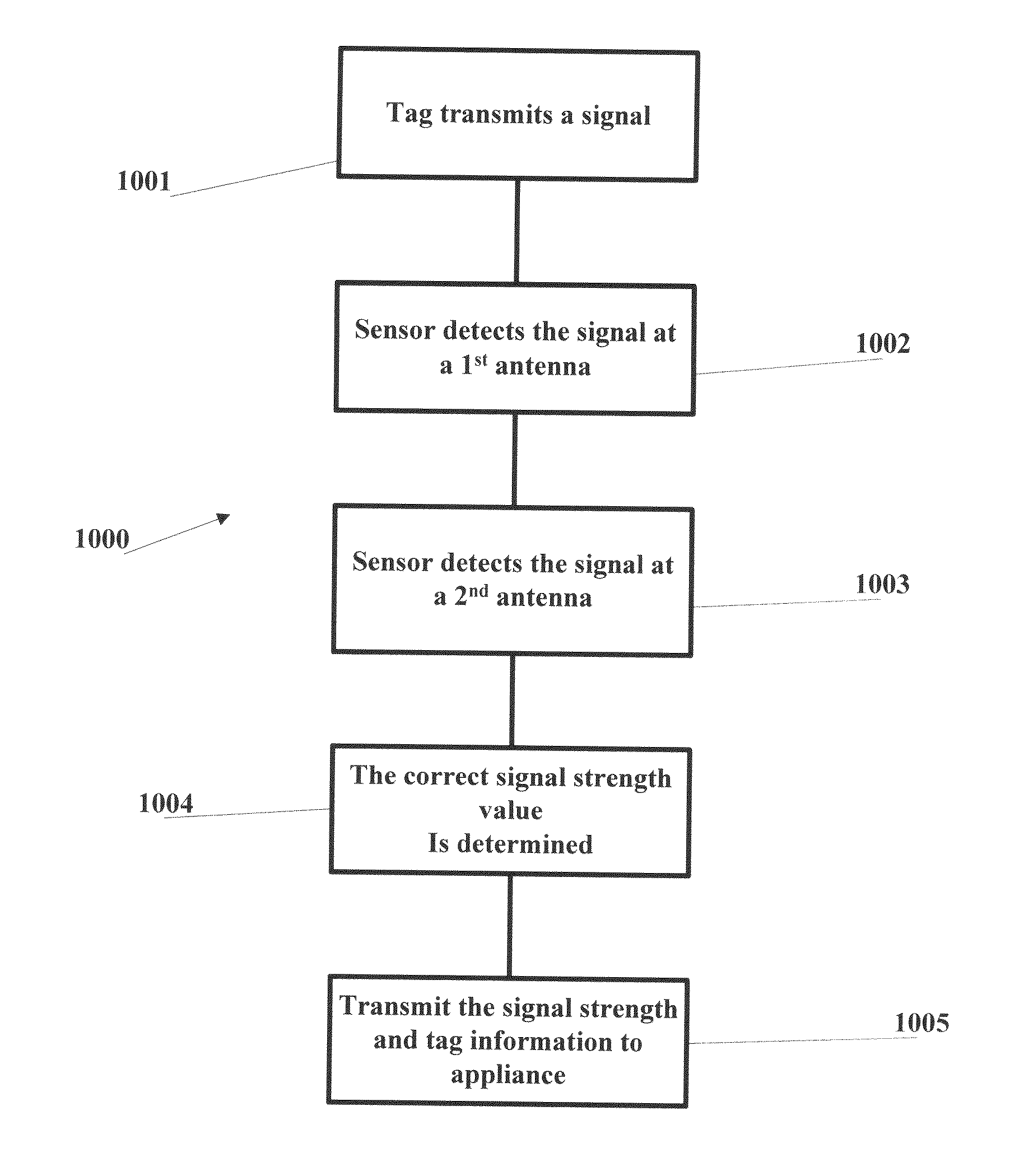
[0020]The present invention is a method and system to improve the accuracy of a received signal strength indication (“RSSI”) based location model to help determine whether or not a mobile radiofrequency (“RF”) transponder is in a particular room.
[0022]Preferably, the present invention utilizes antenna diversity to improve received signal strength signal strength reading when the signals from a tag are above a floor-level of noise in an indoor environment.

Problems solved by technology

Location accuracy associated with radio-frequency-based RTLS (Real-Time Location Systems), suffers from effects related to small-scale fading which often times render location estimates useless.
To date however, no single characteristic has provided accurate location estimates for in-building environments where in-room accuracy is necessary.
However, such an assumption is sometimes erroneous due to common environmental obstacles.
Multipath effects can result in a further located receiver having a stronger received signal from a tagged object than a more proximate receiver to the tagged object, which can result in a mistaken location determination.
However, in an indoor environment, factors such as line out of sign, and multipath affect the free-space path loss model dramatically.
These factors make the received signal strength values unreliable such that the sensors with the stronger received signals are not the ones located closer to the tagged object.
However, this is not always the case because of factors such as transponder antenna orientation and multipath.
The prior art has failed to provide an adequate solution to these problems.

Method used


Image

  • Antenna Diversity For Wireless Tracking System And Method
  • Antenna Diversity For Wireless Tracking System And Method
  • Antenna Diversity For Wireless Tracking System And Method

Examples


Embodiment Construction

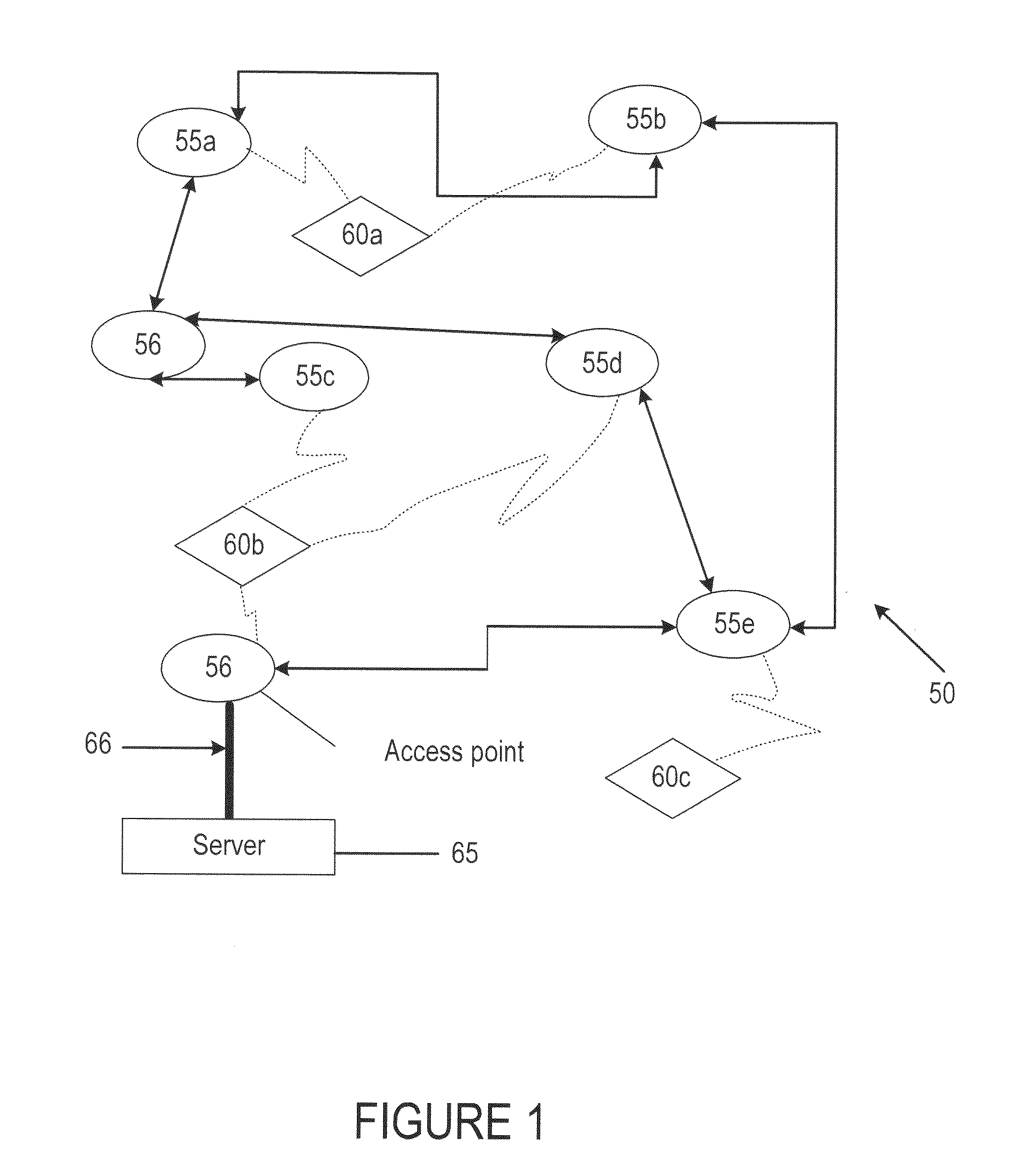
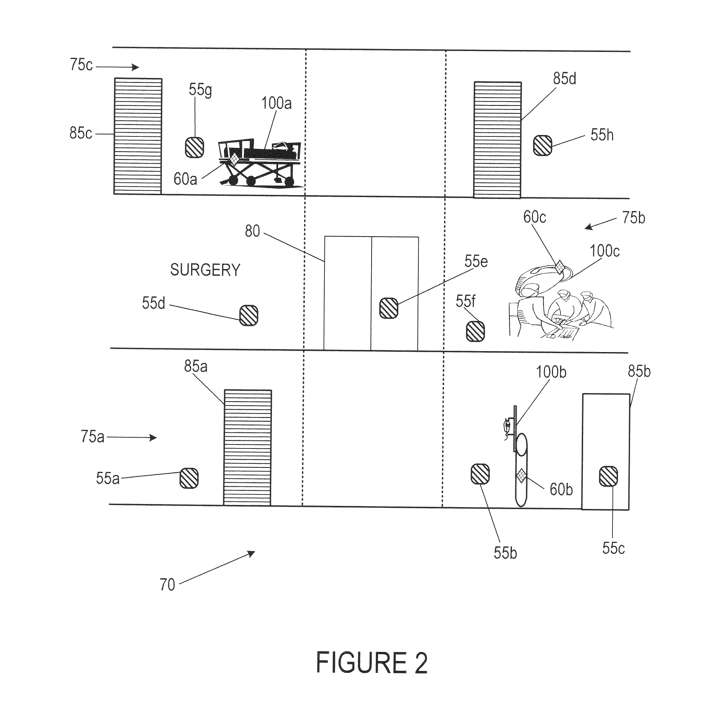
[0048]As shown in FIGS. 1-4, a system for tracking objects within a facility is generally designated 50. The system 50 is capable of determining real-time location of an object 100 within a facility 70. The system 50 preferably includes a plurality of sensors 55, a plurality of bridges 56, a plurality of tags 60 and at least one central processor 65. One example of the components of the system 50 is disclosed in U.S. Pat. No. 7,197,326, for a Wireless Position Location And Tracking System, which is hereby incorporated by reference in its entirety. A more specific example of the sensors 55 is disclosed in U.S. Pat. No. 7,324,824, for a Plug-In Network Appliance, which is hereby incorporated by reference in its entirety.

[0049]The system 50 is preferably employed at a facility 70 such as a business office, factory, home, hospital and / or government agency building. The system 50 is utilized to track and locate various objects positioned throughout the facility 70. The tags 60 preferably...


PUM


Abstract

The present invention provides a solution to determine a real-time location of an object in an indoor facility utilizing the spatial and angular antenna diversity on a sensor. Specifically, the spatial diversity is achieved by placing a second antenna a predetermined distance (which is greater than one-half of the wavelength) away from the first antenna. The angular diversity is obtained by placing the second antenna at ninety degrees (perpendicular) angle of the first antenna.

Description

CROSS REFERENCE TO RELATED APPLICATION[0001]The present application claims priority to U.S. Provisional Patent Application No. 61 / 230,087, filed on Jul. 30, 2009, which is hereby incorporated by reference in its entirety.STATEMENT REGARDING FEDERALLY SPONSORED RESEARCH OR DEVELOPMENT[0002]Not ApplicableBACKGROUND OF THE INVENTION[0003]1. Field of the Invention[0004]The present invention relates to wireless tracking of objects. More specifically, the present invention relates to wireless tracking of objects utilizing antenna diversity.[0005]2. Description of the Related Art[0006]The prior art discusses tracking objects and people using RFID technology.[0007]Location accuracy associated with radio-frequency-based RTLS (Real-Time Location Systems), suffers from effects related to small-scale fading which often times render location estimates useless. To overcome these adverse affects, various mitigation methods have been developed that extract clues from RF-signals such as the angle of...

Claims


Application Information

Patent Timeline
Patent Type & Authority Applications(United States)
IPC IPC(8): H04Q5/22
CPCG01S5/021G01S5/0215H04W64/00G01S5/14G01S5/0252G01S5/0218
Inventor GENG, WEIPERKINS, MATTHEW R.
Owner AWAREPOINT CORPORATION
Learn More