Control circuit and control method for touch panel

a control circuit and touch panel technology, applied in the direction of instruments, computing, electric digital data processing, etc., can solve the problems of not actively supporting multi-touch operations, no technique has been disclosed, and the arrangement cannot distinguish between the output voltage of the panel, so as to increase the panel current and increase the panel current

Active Publication Date: 2011-02-03
ROHM CO LTD
View PDF8 Cites 25 Cited by
  • Summary
  • Abstract
  • Description
  • Claims
  • Application Information

AI Technical Summary

Benefits of technology

[0013]When the user touches two points, a portion of the first resistive film between the two points and a portion of the second resistive film therebetween are connected in parallel. Accordingly, the combined resistance of a path from the first terminal to the second terminal drops, thereby increasing the panel current. The length of the region where

Problems solved by technology

However, such touch panels have been realized only as electrostatic sensor touch panels, and have not been realized as resistive film touch panels.
However, such an arrangement is not capable of distinguishing between the output voltage of the panel in a case in which the user touches two positions (multi-touch operation) and the output voltage thereof in a case in which the use

Method used


Image

  • Control circuit and control method for touch panel
  • Control circuit and control method for touch panel
  • Control circuit and control method for touch panel

Examples


first embodiment

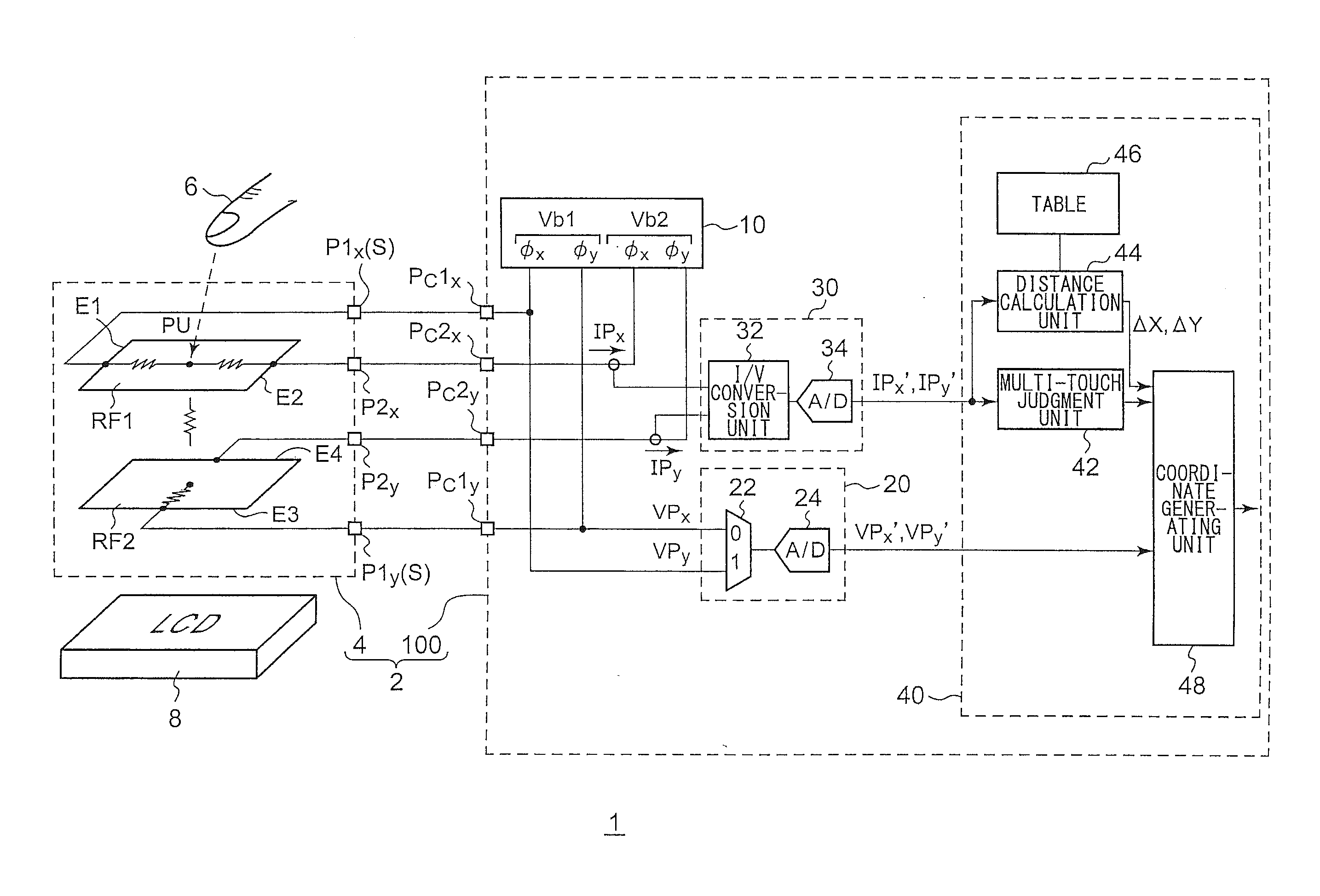
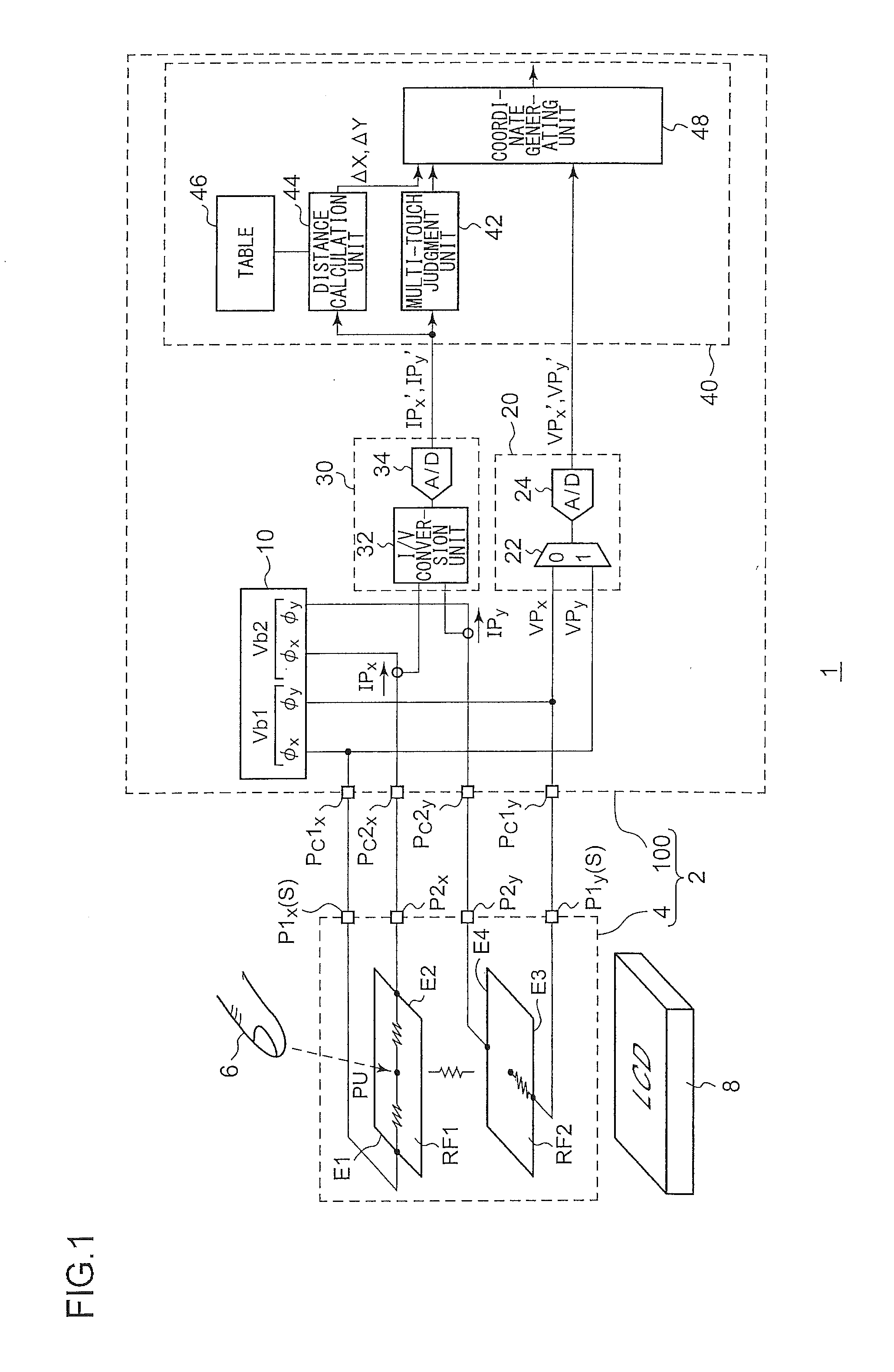
[0058]FIG. 1 is a block diagram which shows a configuration of an electronic device 1 including a touch panel input apparatus (which will simply be referred to as the “input apparatus”) 2 according to a first embodiment. The input apparatus 2 is arranged on a surface layer of an LCD (Liquid Crystal Display) 8, and functions as a touch panel. The input apparatus 2 identifies the X-coordinates and the Y-coordinates of points (positions) touched by the user via a finger, a pen, or the like (which will collectively be referred to as the “finger 6” hereafter).

[0059]The input apparatus 2 includes a touch panel 4 and a control circuit 100. The touch panel 4 is configured as a four-line (four-terminal) resistive film touch panel. The touch panel 4 has a typical configuration, and accordingly, a brief description thereof will be made below.

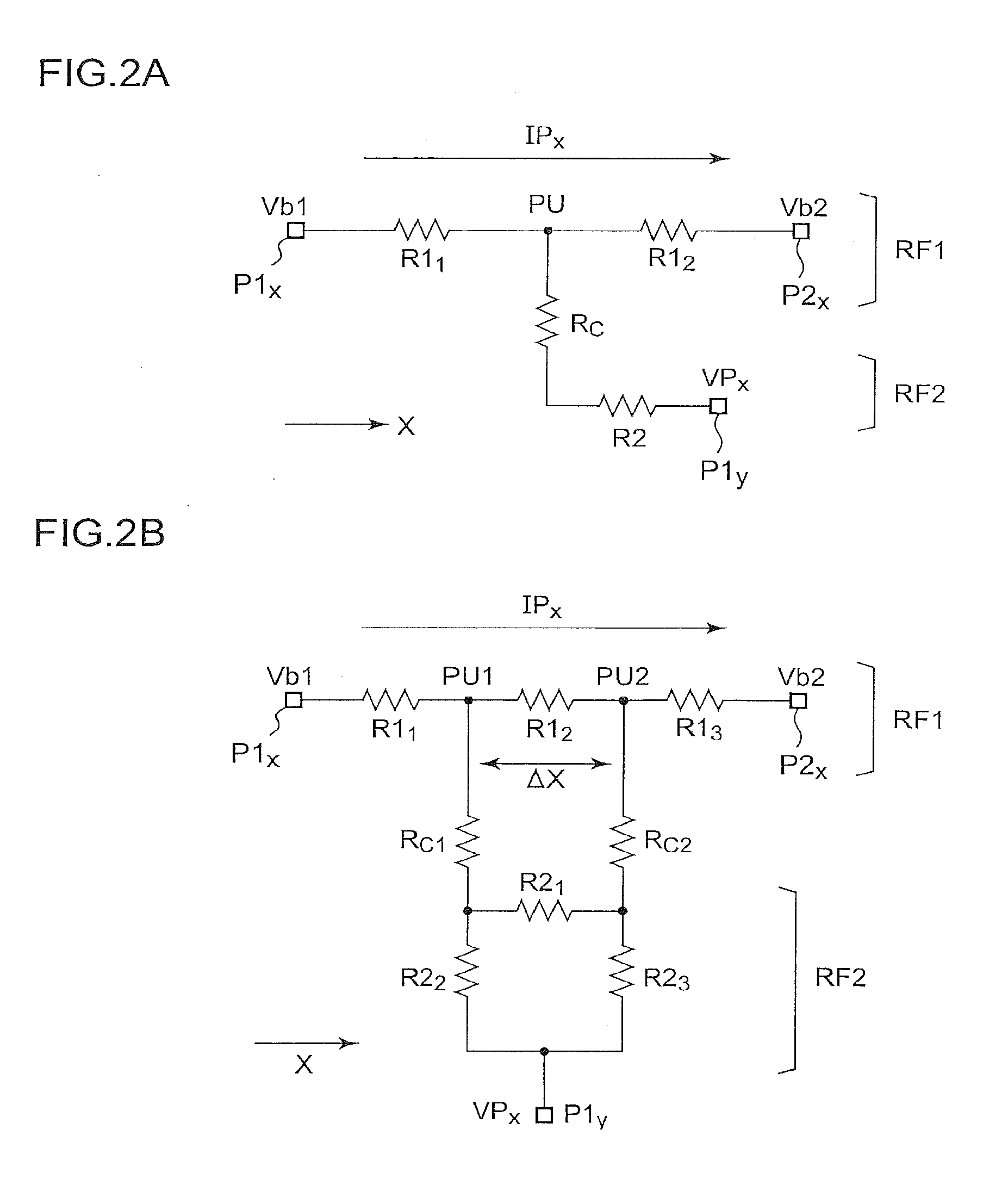
[0060]The touch panel 4 includes a first terminal P1x through a fourth terminal P2y, a first resistive film RF1, and a second resistive film RF2.

[0061]The...

second embodiment

[0127]FIG. 6 is a block diagram which shows a configuration of an electronic device 1 including a touch panel input apparatus (which will simply be referred to as the “input apparatus”) 2 according to a second embodiment. The input apparatus 2 is arranged on a surface layer of an LCD (Liquid Crystal Display) 8, and functions as a touch panel. The input apparatus 2 identifies the X-coordinates and the Y-coordinates of points (positions) touched by the user via a finger, a pen, or the like (which will collectively be referred to as the “finger 6” hereafter).

[0128]The input apparatus 2 includes a touch panel 4 and a control circuit 100. The touch panel 4 is configured as a four-line (four-terminal) resistive film touch panel. The touch panel 4 has a typical configuration, and accordingly, a brief description thereof will be made below.

[0129]The touch panel 4 includes a first terminal P1x through a fourth terminal P2y, a first resistive film RF1, and a second resistive film RF2.

[0130]Th...


PUM


Abstract

A first resistive film is arranged such that one edge thereof is connected to a first terminal, and an edge that is opposite to the aforementioned edge is connected to a second terminal. A second resistive film is arranged with a gap between it and the first resistive film such that one edge thereof is connected to a third terminal. A voltage generating unit applies a predetermined first bias voltage and a predetermined second bias voltage to the first terminal and the second terminal, respectively. A voltage detection unit detects a panel voltage that occurs at the third terminal. A current detection unit detects a panel current that flows through a path including the first terminal, the first resistive film, and the second terminal. A computation unit determines the coordinates touched by the user, based upon the values of the panel voltage and the panel current.

Description

BACKGROUND OF THE INVENTION[0001]1. Field of the Invention[0002]The present invention relates to a resistive film touch panel, and particularly to a technique for detecting a simultaneous touch state (multi-touch state) in which the user touches multiple points.[0003]2. Description of the Related Art[0004]In recent years, it has become mainstream for electronic devices such as computers, cellular phone terminals, PDAs (Personal Digital Assistants), etc., to include an input apparatus which allows the user to operate the electronic device by using the fingers to touch the input device. Known examples of such input devices include resistive film touch panels (touch sensors) (Patent document 1).[Related Art Documents][Patent Documents][Patent Document 1][0005]Japanese Patent Application Laid Open No. 2009-48233[0006]In recent years, there is a demand for a touch panel which supports multi-touch operations. However, such touch panels have been realized only as electrostatic sensor touch...

Claims


Application Information

Patent Timeline
IPC IPC(8): G06F3/045G09G5/00
CPCG06F3/0416G06F2203/04104G06F3/045
Inventor TADA, NAOKIABE, SHINICHISAITO, KOICHIHISA, KAZUNORI
Owner ROHM CO LTD
Why Eureka
Try Eureka