Method for monitoring the influence of ambient noise on stochastic gradient algorithms during identification of linear time-invariant systems

a stochastic gradient and ambient noise technology, applied in speech analysis, instruments, sound producing devices, etc., can solve the problems of significant contamination of the desired audio input signal, distorted estimation of the acoustic feedback path, and sacrifice of gain at and around critical frequencies

Inactive Publication Date: 2011-02-03
OTICON
View PDF10 Cites 24 Cited by
  • Summary
  • Abstract
  • Description
  • Claims
  • Application Information

AI Technical Summary

Benefits of technology

[0014]This has the advantage of providing a criterion which may be used to account for the impact of stationary and non-stationary background noise during the feedback path measurement.
[0015]In an embodiment, the variable filter part provides an estimate (only) of the magnitude-frequency response IH(f)I of the acoustic feedback path. The above criterion has the advantage that it is resistant to changes of the phase response of the feedback path during the measurement.

Problems solved by technology

Unstable systems due to acoustic feedback tend to significantly contaminate the desired audio input signal with narrow band frequency components, which are often perceived as howl or whistle.
The disadvantage of this method is that gain has to be sacrificed at and around critical frequencies.
Background or ambient noise during the measurement influences the convergence behaviour of the NLMS algorithm, contaminates the final state of the AFC filter coefficients and, consequently, yields a distorted estimate of the acoustic feedback path.
However, these methods require additional algorithms like the Fast Fourier Transform (FFT) and do not reflect the implications on the obtained AFC filter coefficients in a straight forward way.

Method used


Image

  • Method for monitoring the influence of ambient noise on stochastic gradient algorithms during identification of linear time-invariant systems
  • Method for monitoring the influence of ambient noise on stochastic gradient algorithms during identification of linear time-invariant systems
  • Method for monitoring the influence of ambient noise on stochastic gradient algorithms during identification of linear time-invariant systems

Examples


example

Measurement of Critical Gain During Fitting

[0048]Consider a threshold level kT for the case U(k)=V(k), k=0, 1, 2, . . . , M, given by

κT≡μ02

[0049]And the initial condition: Filter coefficients h′(i,nNTs=0)=0. That is, the AFC filter coefficients are preferably set to zero at the beginning of the measurement. An example of an initial step size μ0 is 1 / 32.

[0050]To reliably detect a border between an acceptable and an unacceptable amount of ambient noise, the feedback path is considered to be steady state during the measurement procedure.

Measurement Procedure:

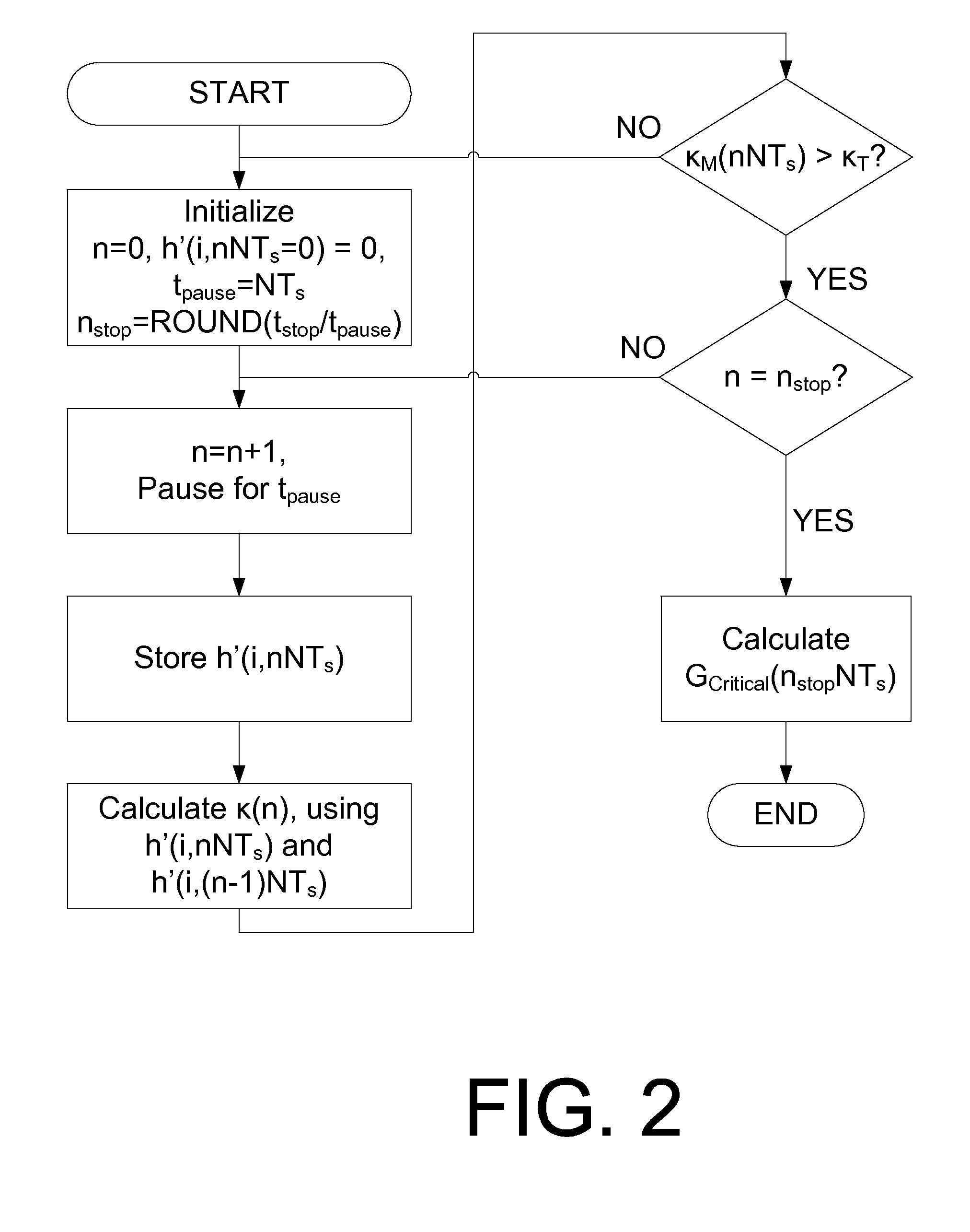
[0051]FIG. 2 shows an algorithm for measuring critical gain in a hearing instrument. In an embodiment, the algorithm comprises the following steps (which are correspondingly illustrated in FIG. 2):[0052]0. Start: Set n=nstart0. Initialize filter coefficients h′(i,nNTs=0)=0. Store ambient noise threshold level kT. Set stop at iteration nstop=ROUND(tstop / tpause), where tpause=NTs, Ts is the sampling period and NεN (integer). Set step...


PUM


Abstract

A hearing aid system and a method of estimating ambient noise in a listening device includes an input transducer and an output transducer, an electrical forward path between the input transducer and the output transducer providing a forward gain, an electrical feedback path comprising an adaptive filter for estimating the acoustic feedback gain from the output transducer to the input transducer. A method determines the quality of a critical gain measurement for a listening device. The method comprises a) monitoring the energy of the first-difference of the filter coefficients of the adaptive filter over time and b) applying a predefined threshold criterion to the change in energy content from one time instance to another to determine an acceptable impact of the ambient noise. This technique may e.g. be used for the fitting of hearing instruments where background noise is variable.

Description

TECHNICAL FIELD[0001]The present invention relates to acoustic feedback cancellation, finding application in hearing aids and further audio devices. The invention relates specifically to a method of estimating an acoustic feedback path in a listening system, e.g. a hearing aid system. The invention relates in particular to a method of estimating the influence of ambient noise on an adaptive filter in steady state.[0002]The invention furthermore relates to a hearing aid system, a computer readable medium and a data processing system.[0003]The invention may e.g. be useful in applications where acoustic feedback is a problem, such as in the fitting of hearing instruments to a user's particular needs.BACKGROUND ART[0004]Frequency dependent acoustic, electrical and mechanical feedback identification methods are commonly used in hearing instruments to ensure their stability. Unstable systems due to acoustic feedback tend to significantly contaminate the desired audio input signal with nar...

Claims


Application Information

Patent Timeline
Patent Type & Authority Applications(United States)
IPC IPC(8): G10K11/16G10L21/02G10L21/0208G10L21/0216
CPCG10L21/0208H04R25/50G10L21/0216
Inventor KUNZLE, BERNHARDBOSTOCK, SARAH
Owner OTICON
Why Eureka
Try Eureka