Method of controlling turbine equipment and turbine equipment

a technology of turbine equipment and equipment, which is applied in the direction of engine starters, turbine/propulsion engine ignition, machines/engines, etc., can solve the problems of reducing the torque applied to the speed reduction gear or the like, restricting the temperature elevating rate of the atomic reactor, and affecting the efficiency of the turbin

Active Publication Date: 2011-02-03
MITSUBISHI HEAVY IND LTD +1
View PDF9 Cites 26 Cited by
  • Summary
  • Abstract
  • Description
  • Claims
  • Application Information

AI Technical Summary

Benefits of technology

According to the method of controlling the turbine equipment and the turbine equipment of the invention, when the temperature of the working fluid flowing to the turbine portion is elevated, by increasing the flow rate of the bypassed working fluid for the predetermined time period and therea

Problems solved by technology

However, a temperature elevating rate of the atomic reactor is restricted, and therefore, even when the closed cycle gas turbine reaches the rated revolution number, the generator is used as the motor for some period of time.
Meanwhile, when the torque applied to the speed reduction gear or the like is changed from the negative torque to the positive torque as described above, there poses a

Method used


Image

  • Method of controlling turbine equipment and turbine equipment
  • Method of controlling turbine equipment and turbine equipment
  • Method of controlling turbine equipment and turbine equipment

Examples


first embodiment

Modified Example of First Embodiment

Next, a modified example of the first embodiment of the invention will be explained in reference to FIG. 6 and FIG. 7.

Although a basic constitution of a power generating equipment of the modified example is similar to that of the first embodiment, the modified example differs from the first embodiment in a control of the first bypass valve. Therefore, according to the embodiment, only the control of the first bypass valve will be explained in reference to FIG. 6 and FIG. 7, and an explanation of other constituent elements or the like will be omitted.

FIG. 6 is a block diagram for explaining the control of the power generating equipment of the modified example.

Further, constituent elements the same as those of the first embodiment are attached with the same notations and an explanation thereof will be omitted.

As shown by FIG. 6, a control portion 150 of a power generating equipment 101 of the embodiment is provided with the second program control po...

second embodiment

Next, a second embodiment of the invention will be explained in reference to FIG. 8 through FIG. 10.

Although a basic constitution of a power generating equipment of the embodiment is similar to that of the first embodiment, the second embodiment differs from the first embodiment in a method of controlling the second bypass valve. Therefore, according to the embodiment, only the method of controlling the second bypass valve will be explained in reference to FIG. 8 through FIG. 10 and an explanation of other constituent element or the like will be omitted.

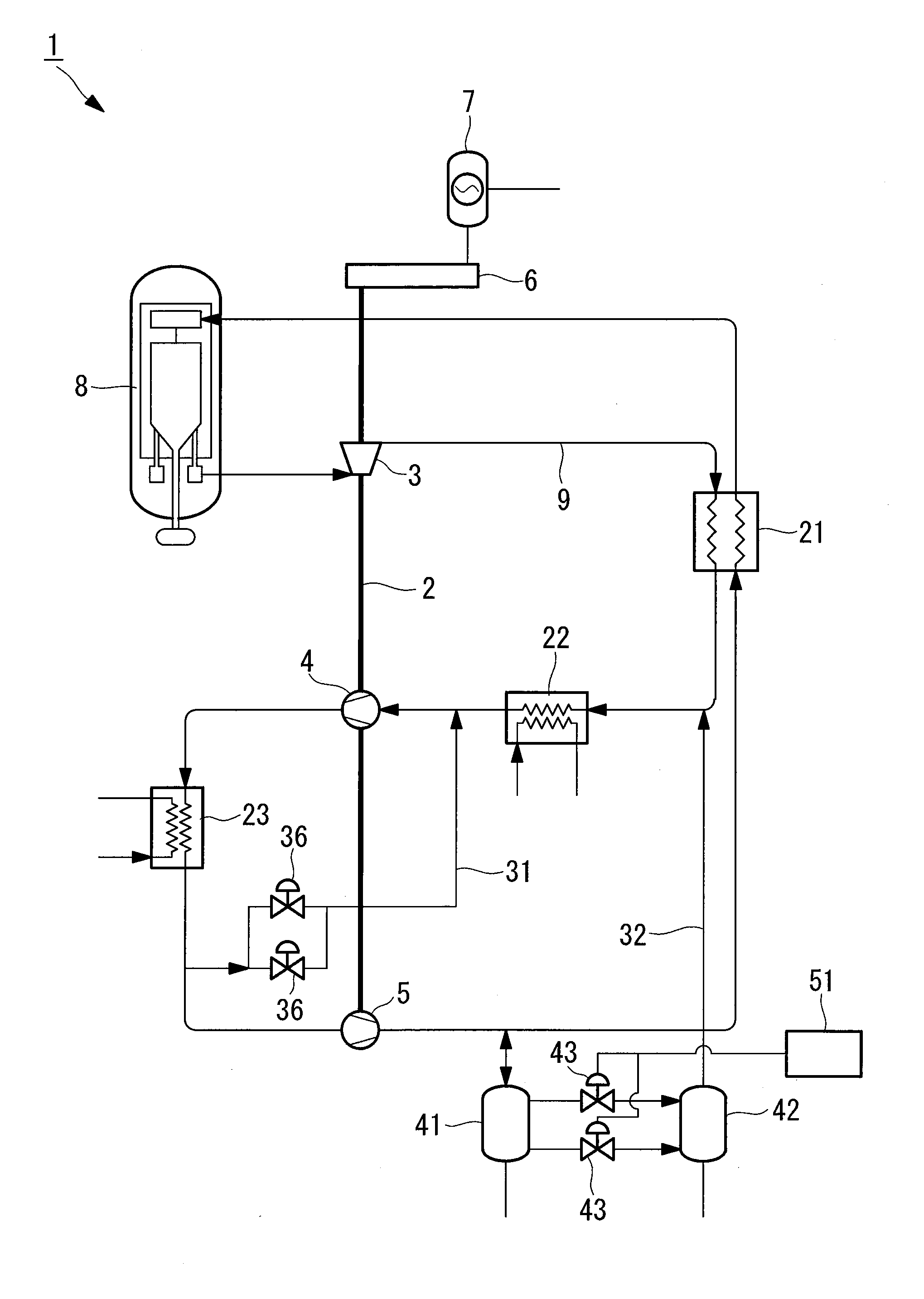
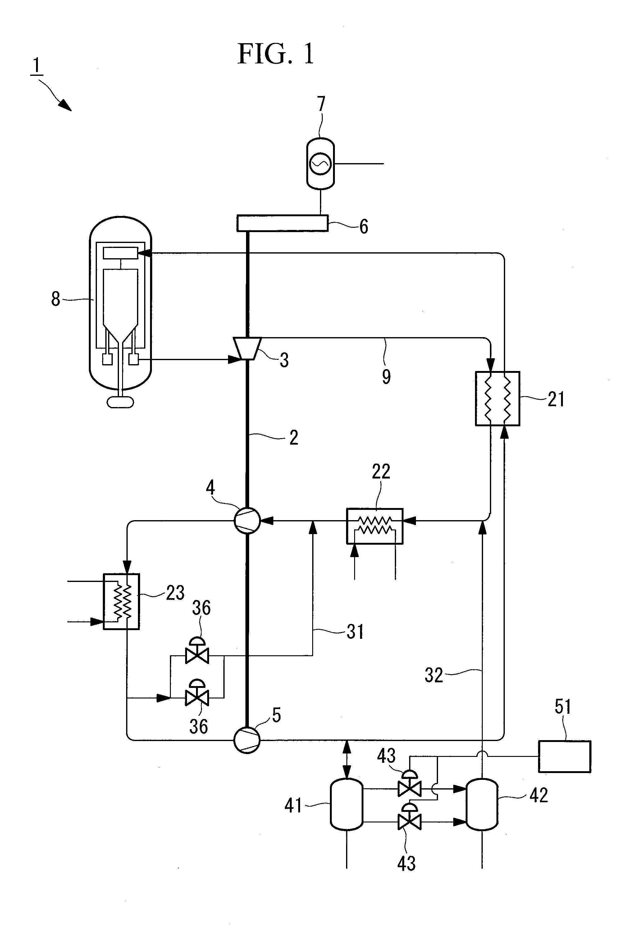
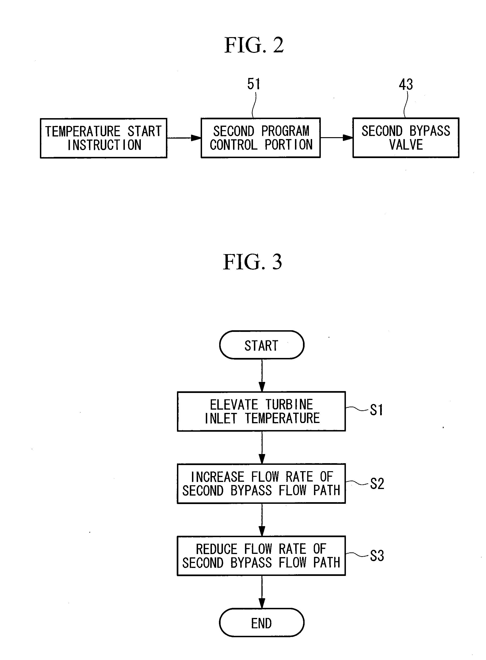
FIG. 8 is a schematic view for explaining a constitution of a power generating equipment according to the embodiment. FIG. 9 is a block diagram for explaining a control of the power generating equipment of FIG. 8.

Further, constituent elements the same as those of the first embodiment are attached with the same notations and an explanation thereof will be omitted.

As shown by FIG. 8 and FIG. 9, a power generating equipment 201 of the e...

third embodiment

Next, a third embodiment of the invention will be explained in reference to FIG. 11 through FIG. 13.

Although a basic constitution of a power generating equipment of the embodiment is similar to that of the second embodiment, the third embodiment differs from the second embodiment in a method of controlling the first bypass valve. Therefore, according to the embodiment, only the method of controlling the first bypass valve will be explained in reference to FIG. 11 through FIG. 13, an explanation of other constituent element or the like will be omitted.

FIG. 11 is a schematic view for explaining a constitution of the power generating equipment according to the embodiment. FIG. 12 is a block diagram for explaining a control of the power generating equipment of FIG. 11.

Further, constituent elements the same as those of the second embodiment are attached with the same notations and an explanation thereof will be omitted.

As shown by FIG. 11 and FIG. 12, a power generating equipment 301 of ...


PUM


Abstract

To provide a method of controlling a turbine equipment and a turbine equipment capable of carrying out a starting operation of controlling a load applied to a speed reducing portion while complying with a restriction imposed on an apparatus provided at a turbine equipment. The invention is characterized in including a temperature elevating step (S1) of elevating a temperature of a working fluid flowing to the turbine portion, a flow rate increasing step (S2) of increasing a flow rate of a working fluid bypassed from a delivery side to a suction side of the compressing portion when a temperature of the working fluid flowing to the turbine portion is elevated by a heat source portion, and a flow rate reducing step (S3) of reducing the flow rate of the bypassing working fluid after an elapse of a predetermined time period after increasing the flow rate of the bypassing working fluid.

Description

TECHNICAL FIELDThe present invention relates to a method of controlling a turbine equipment and a turbine equipment, particularly relates to a method of controlling a turbine equipment and a turbine equipment preferably used in a closed cycle gas turbine for circulating a working fluid in a closed system by using an atomic reactor or the like for a heat source.BACKGROUND ARTAccording to a closed cycle gas turbine of circulating a working fluid in a closed system by using an atomic reactor or the like for a heat source, an equipment capacity of a motor used for only operating to accelerate speed in starting, an electric apparatus SFC (Static Frequency Converter) or the like by using a generator as a motor is made to be as small as possible in order to achieve a reduction in plant construction cost.Therefore, according to the closed cycle gas turbine, a speed is elevated to a rated revolution number in a state of reducing an amount of filling a working fluid in the closed system, for ...

Claims


Application Information

Patent Timeline
IPC IPC(8): F04D27/02F04D15/00
CPCF01K13/02F02C1/05F05D2260/85F02C9/18F02C1/10F02C3/34F02C7/26
Inventor ONO, HITOISONODA, TAKASHITOCHITANI, NAOTOKATO, MAKOTOUMAYA, MASAHIDEFUJII, FUMINORI
Owner MITSUBISHI HEAVY IND LTD
Why Eureka
Try Eureka