Cooling structure of turbine airfoil

a cooling structure and turbine technology, applied in the direction of blade accessories, engine fuctions, machines/engines, etc., can solve the problems of affecting engine performance, likely backflow of cooling air at the holes, and ineffective cooling of the turbine airfoil, so as to reduce the flow rate of cooling air. the effect of cooling the turbine airfoil

Active Publication Date: 2011-02-03
IHI CORP +1
View PDF24 Cites 31 Cited by
  • Summary
  • Abstract
  • Description
  • Claims
  • Application Information

AI Technical Summary

Benefits of technology

[0014]The invention has been made so as to solve the above-mentioned problem. That is, an object of the invention is to provide a cooling structure for a turbine airfoil capable of effectively cooling the turbine airfoil (in particular, the airfoil leading edge) and decreasing the cooling air flow rate as compared with a prior art.

Problems solved by technology

For this reason, there are many cases where the airfoil leading edge does not obtain the necessary cooling effectiveness only by convection cooling at the cooling sidewall.
Significant quantities of holes are required to cool the turbine airfoil with heat absorption, but if the opening area of the holes is increased, the cooling air is likely to flow backwards at the holes.
In this instance, however, there is a problem in that the flow rate of the cooling air is increased, so that engine performance deteriorates.

Method used


Image

  • Cooling structure of turbine airfoil
  • Cooling structure of turbine airfoil
  • Cooling structure of turbine airfoil

Examples


example

[0064]In the configuration shown in FIGS. 6A and 6B, a cooling performance test was performed for the case of Px=10 mm, Py=10 mm, d1=4 mm, d2=4 mm, d3=4 mm, and h=H. In the cooling performance test, a test piece having the cooling structure was installed under combustion gas, and the cooling air was supplied into the test piece. The surface temperature was measured by an infrared camera and the flow rate of the cooling air was measured by a flowmeter.

[0065]FIGS. 7A and 7B are views illustrating the test results, in which FIG. 7A is the cooling effectiveness and FIG. 7B is the cooling air flow rate.

[0066]In FIG. 7A, the horizontal axis refers to the ratio of mass flux Mi of cooling air to hot gas, and the vertical axis refers to cooling effectiveness. In the figure, a solid line indicates the present invention, and a dashed line indicates a comparative example with no heat-transfer promoting projection 14.

[0067]Further, in FIG. 7B, the horizontal axis refers to a pressure ratio Pc·in...


PUM


Abstract

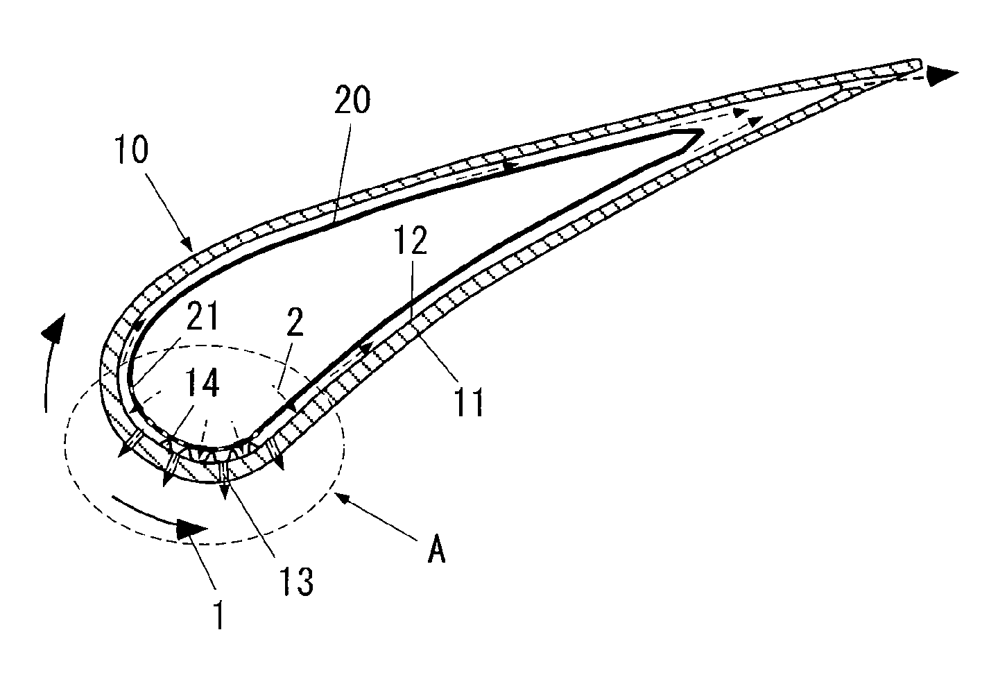
A cooling structure of a turbine airfoil cools a turbine airfoil (10) exposed to hot gas (1), using cooling air (2) of a temperature lower than that of the hot gas. The turbine airfoil (10) includes an external surface (11), an internal surface (12) opposite to the external surface, a plurality of film-cooling holes (13) blowing the cooling air from the internal surface toward the external surface to film-cool the external surface, and a plurality of heat-transfer promoting projections (14) integrally formed with the internal surface and protruding inwardly from the internal surface. The turbine airfoil further includes a hollow cylindrical insert (20) which is positioned inside the internal surface of the turbine airfoil and to which the cooling air is supplied. The insert has a plurality of impingement holes (21) for impingement-cooling the internal surface (12).

Description

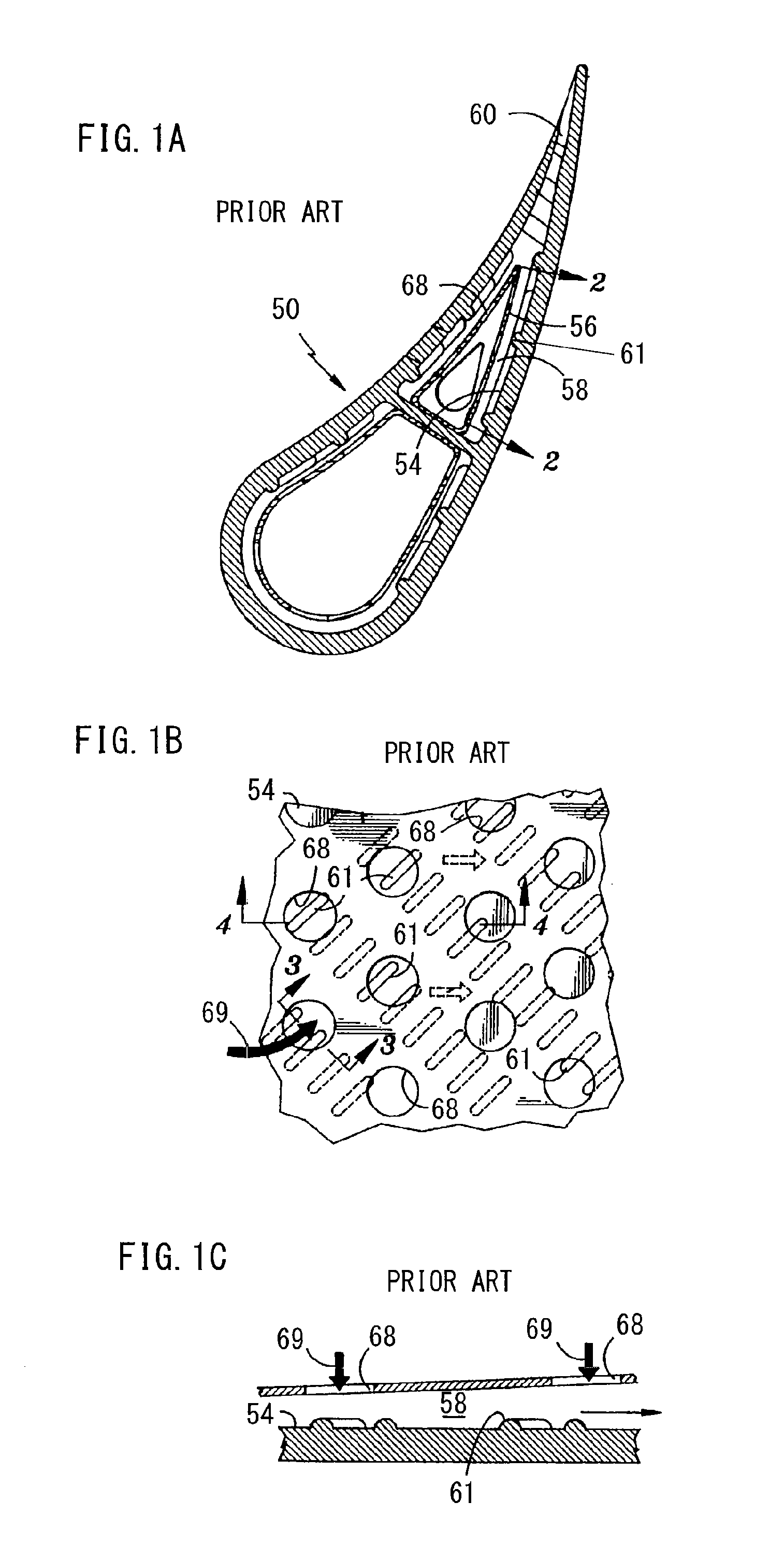
BACKGROUND OF THE INVENTION[0001]1. Technical Field of the Invention[0002]The present invention relates to a cooling structure of a turbine airfoil in a gas turbine for aviation or industry.[0003]2. Description of the Prior Art[0004]In the turbine airfoil of a gas turbine for aviation or industry, since the external surface is exposed to hot gas (e.g., 1000° C. or more) during operation, the turbine airfoil is generally cooled from the inside thereof by flowing cooling gas (e.g., cooling air) into the inside so as to prevent the turbine airfoil from overheating.[0005]In order to improve the cooling performance of the turbine airfoil, several proposals have been suggested (e.g., Patent Documents 1 to 3).[0006]In the gas turbine airfoil disclosed in Patent Document 1, the cooling air is fed from a tube 56 inside an airfoil 50, as shown in FIGS. 1A, 1B and 1C. The cooling air 69 flows toward the internal surface 54 of the airfoil through flow openings 68 of the tube 56. Small, elongate...

Claims


Application Information

Patent Timeline
Patent Type & Authority Applications(United States)
IPC IPC(8): F01D5/18
CPCF01D5/186F01D5/189F05D2240/121F05D2240/122F05D2240/303F05D2260/205F05D2260/201F05D2260/2212F05D2260/22141F05D2260/2214F05D2240/304
Inventor NAKAMATA, CHIYUKIYAMANE, TAKASHIFUKUYAMA, YOSHITAKABAMBA, TAKAHIRO
Owner IHI CORP
Why Eureka
Try Eureka