
Methods of making reactive composite materials and resulting products

Inactive Publication Date: 2011-02-03
NANOFOIL CORP
View PDF5 Cites 23 Cited by
  • Summary
  • Abstract
  • Description
  • Claims
  • Application Information

AI Technical Summary

Benefits of technology

[0019]In accordance with the invention, RCMs are fabricated by a series of mechanical deformation steps. In the first deformation step, an assembly of reactive layers and / or particles is plastically deformed to reduce its cross sectional area by one-half or more. This severe initial deformation substantially eliminates the tendency of deformed layers to delaminate and eliminates the necessity of using specially cleaned metal layers. Portions of the deformed sheets are stacked or bent into a new assembly, and the new assembly is then deformed. The steps of assembly and deformation are repeated a sufficient number of times that the resulting materials are only locally layered but have relatively uniform reaction velocity and heat generating characteristics predictable by stochastic models derived herein. The resulting product is a controllable, locally layered reactive composite material (LLRCM) that can be fabricated quickly and is useful in a wide variety of applications.

Problems solved by technology

This fabrication of the rolled foils was time consuming and difficult.
In addition, the manual folding of sheet stock does not easily lend itself to large-scale production.
However, when many metal layers are rolled at once, these layers tend to delaminate, causing degradation of the resulting foil.
Such separation also permits undesirable oxidation of interlayer surfaces and impedes unification of the layers by cold welding.
Moreover repeated rolling passes tended to distort the layered structures in ways not then predictable, producing necking, elongation or rupture in individual layers, changing the relative thicknesses of the layers, decreasing the ductility of the resulting foil and, significantly, preventing the fabrication of a foil with prescribed reaction velocity and heat generating characteristics.
However, because physical vapor deposition builds foils atom by atom or molecule by molecule, it is not well-suited to the formation of thick layers and thick foils.

Method used


Image

  • Methods of making reactive composite materials and resulting products
  • Methods of making reactive composite materials and resulting products
  • Methods of making reactive composite materials and resulting products

Examples


Embodiment Construction

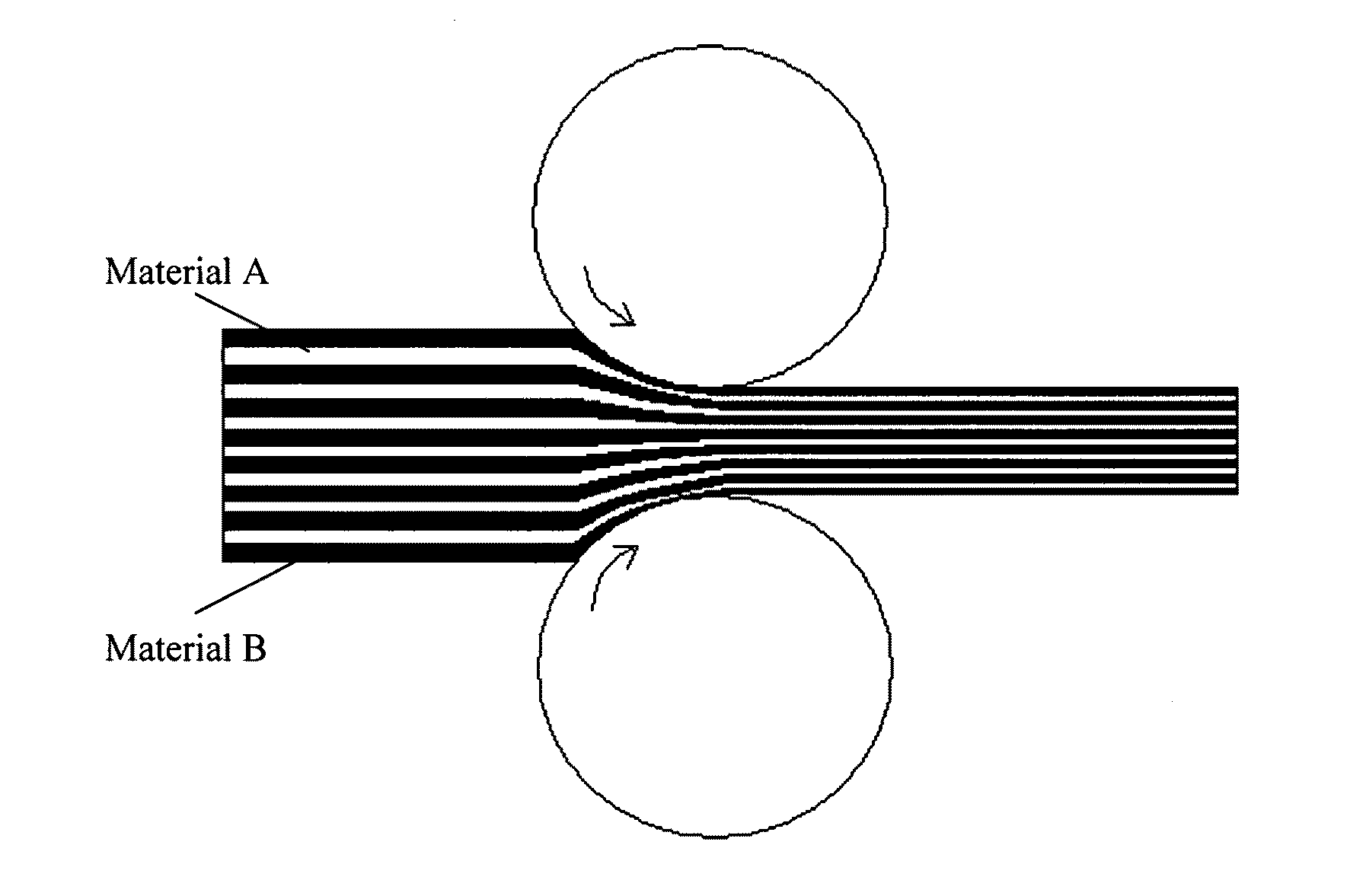
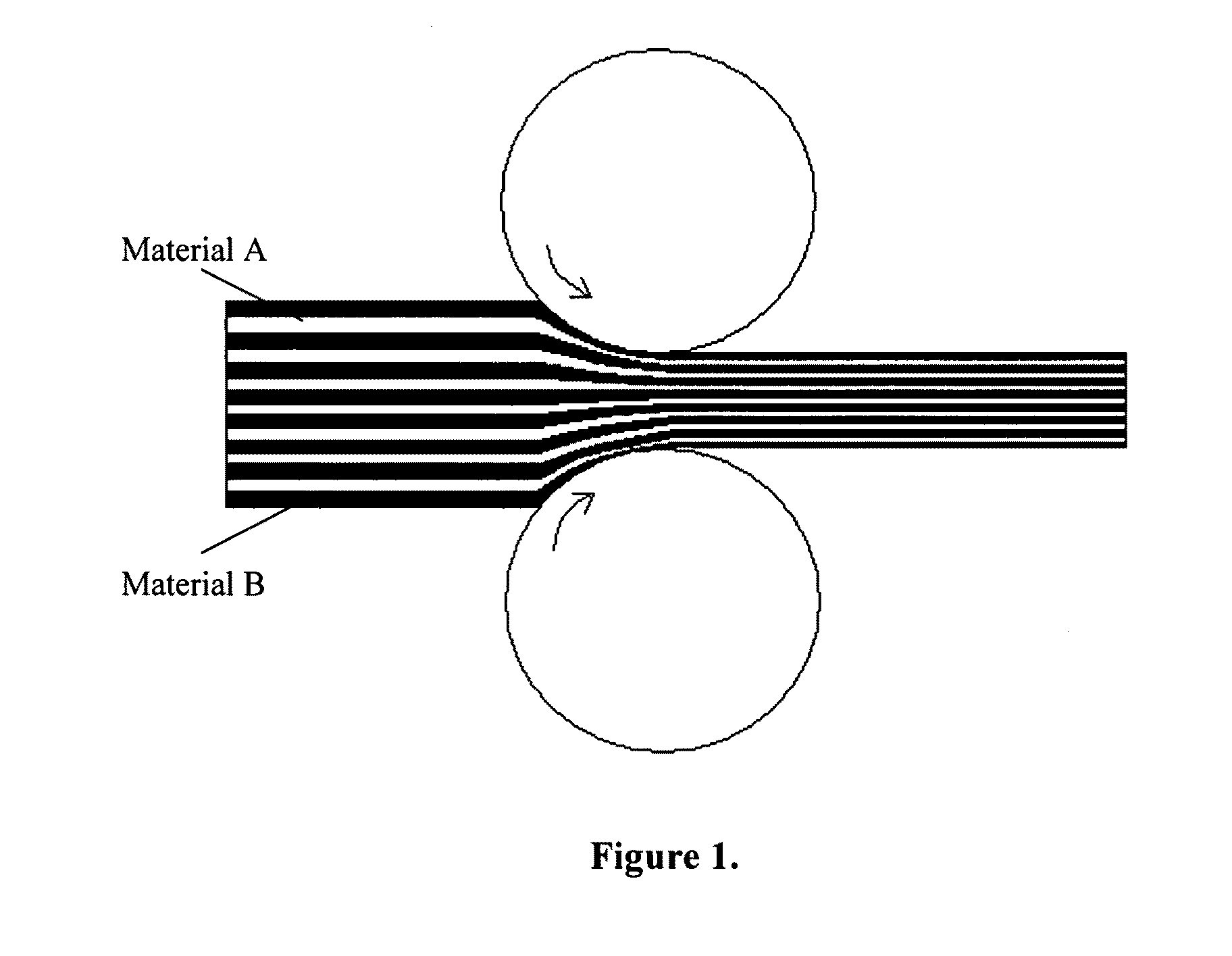
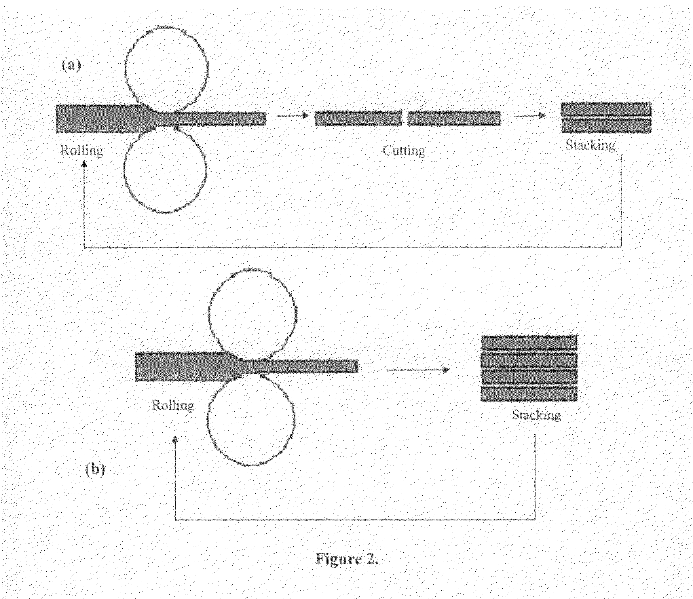
[0063]This description is divided into two parts: Part I describes reactive composite materials and their fabrication in accordance with the invention; and Part II describes the beneficial features and characteristics of the resulting products in relation to fabrication parameters.

[0064]I. Methods of Fabricating Reactive Composite Materials

[0065]Recent developments in reactive multilayer technology have shown that it is possible to carefully control both the heat of the reaction as well as the reaction velocity, and have also provided alternative means for fabricating nanostructured multilayers. For instance, it has been demonstrated that the velocities, heats, and temperatures of the reactions can be controlled in uniformly layered RCMs by varying the thicknesses of the alternating layers1,2. It has also been shown that the heats of reaction can be controlled by modifying the multilayer composition, or by low-temperature annealing of the reactive multilayers after their fabrication...


PUM

PropertyMeasurementUnit
Temperatureaaaaaaaaaa
Lengthaaaaaaaaaa

Abstract

Applicants have discovered new composite materials and have developed a variety of new ways of making reactive composite materials (RCMs) and methods of controlling the properties and characteristics of the materials that are pertinent to numerous new or improved applications. This patent application is directed to new and improved ways of making reactive composite materials using mechanical deformation and making such materials with controlled, predictable characteristics. This application is also directed toward useful applications of the resulting materials.In accordance with the invention, RCMs are fabricated by a series of mechanical deformation steps. In the first deformation step, an assembly of reactive layers and / or particles is plastically deformed to reduce its cross sectional area by one-half or more. This severe initial deformation substantially eliminates the tendency of deformed layers to delaminate and eliminates the necessity of using specially cleaned metal layers. Portions of the deformed sheets are stacked or bent into a new assembly, and the new assembly is then deformed. The steps of assembly and deformation are repeated a sufficient number of times that the resulting materials are only locally layered but have relatively uniform reaction velocity and heat generating characteristics predictable by stochastic models derived herein. The resulting product is a controllable, locally layered reactive composite material (LLRCM) that can be fabricated quickly and is useful in a wide variety of applications.

Description

CROSS-REFERENCE TO RELATED APPLICATIONS[0001]This application claims the benefit of U.S. Provisional Application Ser. No. 60 / 692,822 filed by T. P. Weihs, et al., on Jun. 22, 2005.[0002]This application is also a continuation-in-part of U.S. application Ser. No. 10 / 814,243 filed by T. P. Weihs et al. on Apr. 1, 2004 (“Hermetically Sealed Product and Related Methods of Manufacture”) which, in turn, claims the benefit of Ser. No. 60 / 461,196 filed Apr. 9, 2003.[0003]This application is further a continuation-in-part of U.S. application Ser. No. 10 / 959,502 filed by T. P. Weihs et al. on Oct. 7, 2004 (“Methods of Controlling Multilayer Foil Ignition”) which claims the benefit of Ser. No. 60 / 509,526 filed Oct. 9, 2003.[0004]This application is also a continuation-in-part of U.S. application Ser. No. 10 / 976,877 filed by T. P. Weihs et al. on Nov. 1, 2004 (“Methods and Device for Controlling Pressure in Reactive Multilayer Joining and Resulting Product”) which, in turn, claims the benefit o...

Claims


Application Information

Patent Timeline
IPC IPC(8): B32B3/10C21D8/00C06B45/12C06B45/16B21D31/00B21H1/22
CPCY10T428/24851B32B15/01
Inventor XUN, YUWEILUNKING, DAVIDBESNOIN, ETIENNEHEERDEN, DAVID VANWEIHS, TIMOTHY P.KNIO, OMAR
Owner NANOFOIL CORP
Learn More