Battery system and electric vehicle including the same
a battery system and electric vehicle technology, applied in the field of battery systems, can solve problems such as increasing costs, and achieve the effects of increasing capacity, simplifying configuration, and suppressing increased costs
- Summary
- Abstract
- Description
- Claims
- Application Information
AI Technical Summary
Benefits of technology
Problems solved by technology
Method used
Image
Examples
first embodiment
[1] First Embodiment
[0065]Hereinafter, description will be made of a battery system according to a first embodiment while referring to the drawings. Note that the battery system according to the present embodiment is mounted on an electric vehicle (an electric automobile, for example) using electric power as a driving source.
[0066](1) Configuration of the Battery System
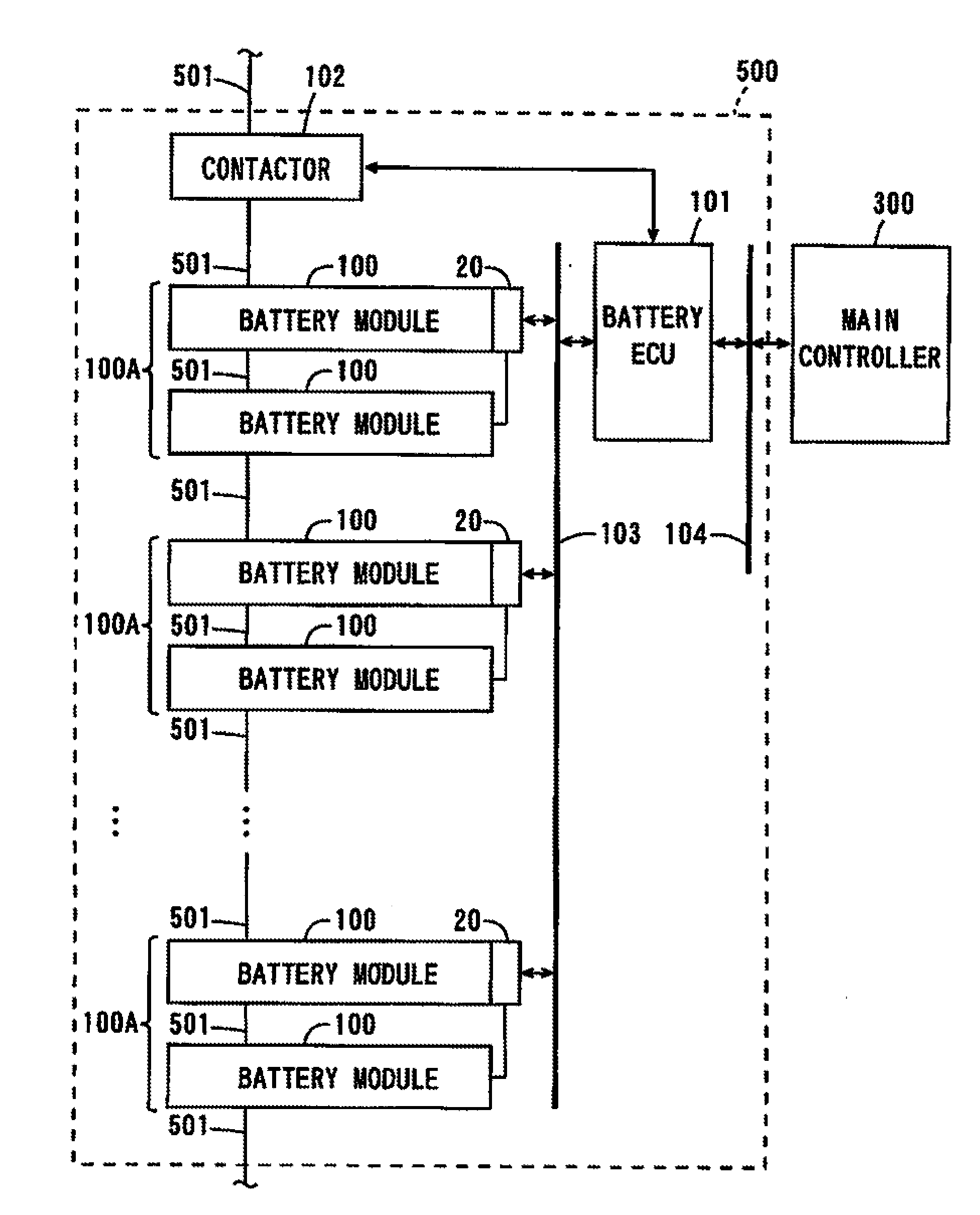
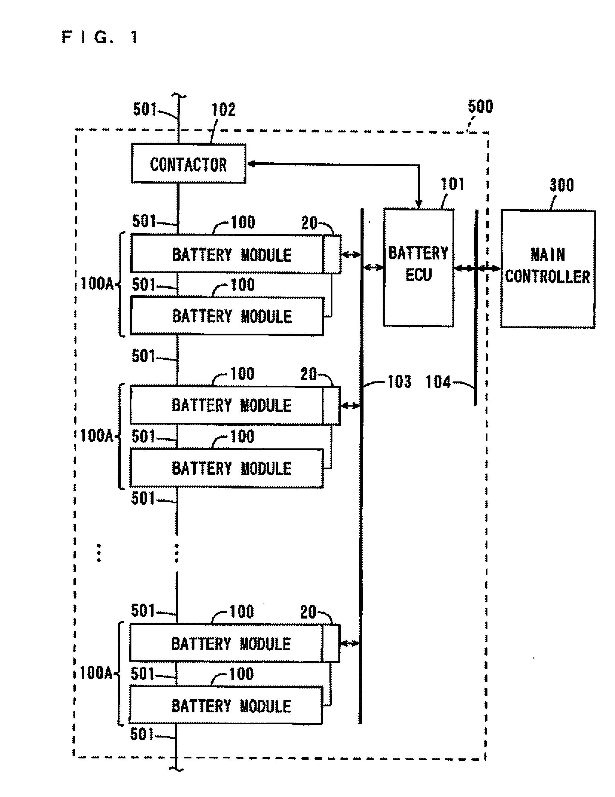
[0067]FIG. 1 is a block diagram showing the schematic configuration of the battery system according to the first embodiment. As shown in FIG. 1, main constituents of the battery system 500 are a plurality of battery modules 100, a plurality of detecting circuits 20, a battery ECU (Electronic Control Unit) 101 and a contactor 102, and the battery system 500 is connected to a main controller 300 of the electric vehicle via a bus 104. The battery system 500 includes a casing that is not shown. The components of the battery system 500 are housed in the casing.
[0068]The plurality of battery modules 100 of the battery syste...
second embodiment
[2] Second Embodiment
[0144]Description will be made of a battery system according to a second embodiment while referring to differences from the battery system 500 according to the first embodiment.
[0145]FIG. 11 is a plan view showing the arrangement of a module group included in the battery system according to the second embodiment.
[0146]As shown in FIG. 11, a module group 100B includes three battery modules 100a, 100b, 100c in the battery system according to the present embodiment. One detecting circuit 20 is provided in common for the three battery modules 100a, 100b, 100c.
[0147]In the present embodiment, the three battery modules 100c, 100b, 100a are arranged to line up in this order along the X-direction (the direction in which the plurality of battery cells 10 line up).
[0148]The printed circuit board 21 including the detecting circuit 20 is attached to an end surface of the one battery module 100a and positioned between end surfaces, which are in close proximity to each other...
third embodiment
[3] Third Embodiment
[0152]Description will be made of a battery system according to a third embodiment while referring to differences from the battery system 500 according to the first embodiment.
[0153]FIG. 12 (a) is a plan view showing the arrangement of a module group in the battery system according to the third embodiment, FIG. 12 (b) is a diagram showing one surface of the printed circuit board 21 of FIG. 12 (a), and FIG. 12 (c) is a diagram showing the other surface of the printed circuit board 21 of FIG. 12 (a).
[0154]In the battery system according to the present embodiment, the module group 100C includes two battery modules 100a, 100b as shown in FIG. 12 (a). Similarly to the battery system 500 according to the first embodiment, the one detecting circuit 20 is provided in common for the two battery modules 100a, 100b.
[0155]As shown in FIG. 12 (a), the two battery modules 100a, 100b are arranged to line up along the X-direction (the direction in which the plurality of battery...
PUM
 Abstract
Description
Claims
Application Information
 - R&D
- Intellectual Property
- Life Sciences
- Materials
- Tech Scout
- Unparalleled Data Quality
- Higher Quality Content
- 60% Fewer Hallucinations
Browse by: Latest US Patents, China's latest patents, Technical Efficacy Thesaurus, Application Domain, Technology Topic, Popular Technical Reports.
© 2025 PatSnap. All rights reserved.Legal|Privacy policy|Modern Slavery Act Transparency Statement|Sitemap|About US| Contact US: help@patsnap.com


