

Polishing method for a workpiece and polishing tool used for the polishing method
- Summary
- Abstract
- Description
- Claims
- Application Information
AI Technical Summary
Benefits of technology
Problems solved by technology
Method used
Image

Examples
first embodiment
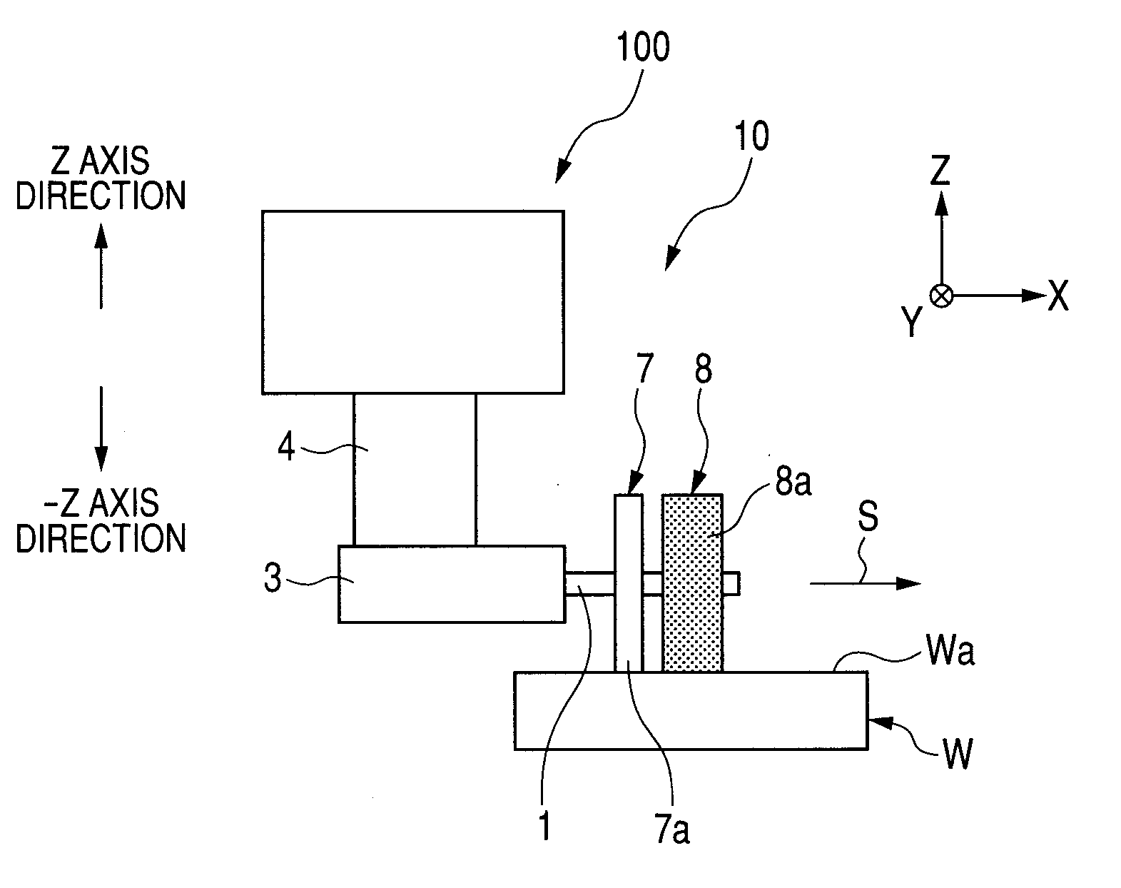
[0017]A polishing apparatus 100 illustrated in FIG. 1 performs processing, with use of a polishing tool 10 mounted to a polishing apparatus main body, on a surface of a workpiece W placed on an XY stage (not shown). The workpiece W has a surface Wa, which is a flat surface, a spherical surface, or a non-horizontal surface such as a non-axisymmetric free-form surface. The workpiece W is, for example, an optical element such as a lens or a mirror, or a die for molding an optical element. The polishing tool 10 includes a rotation shaft 1, and at least two disk-like polishing bodies 7, 8 provided to the rotation shaft 1 so as to be adjacent to each other. The rotation shaft 1 of the polishing tool 10 is fixed to a tool rotating device of the polishing apparatus 100, whereby the polishing tool 10 is supported to be rotatable relative to the polishing apparatus main body. The first polishing body 8 and the second polishing body 7 respectively have outer peripheral surfaces serving as work...
second embodiment
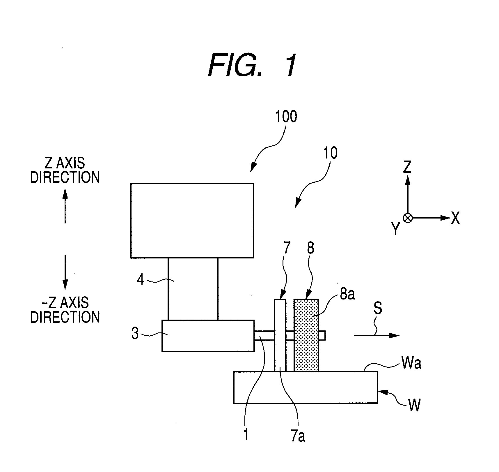
[0026]Next, a second embodiment of the present invention is described. FIG. 2A illustrates a polishing tool 11 according to the second embodiment. Portions identical to those of FIG. 1 are denoted by the same symbols, and description thereof is omitted. The polishing tool 11 includes the rotation shaft 1, and three disk-like polishing bodies 7, 8, and 9 provided to the rotation shaft 1 so as to be adjacent to each other. The rotation shaft 1 of the polishing tool 11 is fixed to the tool rotating device 3 of the polishing apparatus 100, whereby the polishing tool 11 is supported to be rotatable relative to the polishing apparatus main body. The first polishing body 8, the second polishing body 7, and the third polishing body 9 respectively have outer peripheral surfaces serving as working surfaces 8a, 7a, and 9a. The first polishing body 8, the second polishing body 7, and the third polishing body 9 are fixed onto the rotation shaft 1 passing through the center portion of each disk-l...
third embodiment
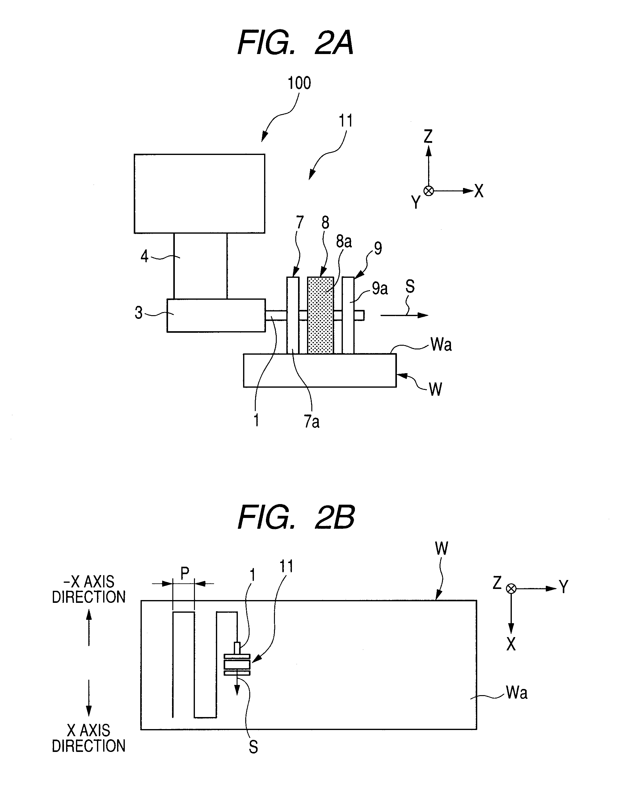
[0033]Next, a third embodiment of the present invention is described. FIG. 3A illustrates a polishing tool 12 according to the third embodiment. Portions identical to those of FIGS. 2A and 2B are denoted by the same symbols, and description thereof is omitted.
[0034]In FIG. 3A, multiple grooves 9b with a depth (for example, 0.35 mm) of from 0.1 mm to a size corresponding to the thickness of the polishing body 9 are formed in the outer peripheral surface 9a of the polishing body 9 at intervals of 2° or less in a direction parallel to the rotation shaft. In the case where the depth of each of the grooves is extremely shallow, when the polishing body 9 is pressed, the polishing body 9 is deformed so that bottoms of the grooves are brought into contact with the surface Wa of the workpiece W. Thus, the polishing body 9 cannot exert an effect of the grooves. The multiple grooves 9b are formed in the outer peripheral surface 9a of the polishing body 9, and hence it is possible to suppress f...
PUM
| Property | Measurement | Unit |
|---|---|---|
| Time | aaaaa | aaaaa |
| Porosity | aaaaa | aaaaa |
| Deformation enthalpy | aaaaa | aaaaa |
Abstract
Description
Claims
Application Information