Power transmission device and power transmission system

Active Publication Date: 2011-02-03
NIPPON SOKEN +1
View PDF10 Cites 21 Cited by
  • Summary
  • Abstract
  • Description
  • Claims
  • Application Information

AI Technical Summary

Benefits of technology

[0012]In the preferred mode of the invention, the power transmission apparatus further comprises a rotating shaft, a first clutch joined directly to the rotating shaft, and a second clutch joined directly to the rotating shaft. The rotating shaft is coupled mechanically to the second rotor of the power split mechanism and works to rotate with rotation of the second rotor The first clutch works to connect the rotating shaft mechanically to the first rotor. The second clutch works to connect the rotating shaft mechanically to the third rotor. The direct mechanical connections of the first and second clutches to the same rotating shaft permits the first and second clutches to be disposed close to each other, thereby facilitating ease of layout of the first and second clutches. In the case where the first and second clutches are of a hydraulic type, it results in ease of designing a hydraulic path and permits the whole of the power transmission apparatus to be reduced in size.
[0038]According to the second aspect of the invention, there is provided a power transmission system for a vehicle which comprises the above described power transmission apparatus, and a load torque applying mechanism which works to control an operation of the first power transmission mechanism to apply a load torque of the internal combustion engine to the starting rotor when it is required to brake the vehicle. This compensates for a lack in load torque, as produced by a regenerative operation of an electric rotating machine, for producing a braking force.

Problems solved by technology

The power transmission device, as described above, is so designed that the rotors of the planetary gear train which are connected mechanically to the power source and the driven wheels are fixed, which may result in unsuitable mechanical connections among the power source, the power-driven member, and the power transmission device which leads to mismatching of the gear ratio of a power transmission path between the power source and the power-driven member with running conditions of the vehicle.

Method used


Image

  • Power transmission device and power transmission system
  • Power transmission device and power transmission system
  • Power transmission device and power transmission system

Examples


first embodiment

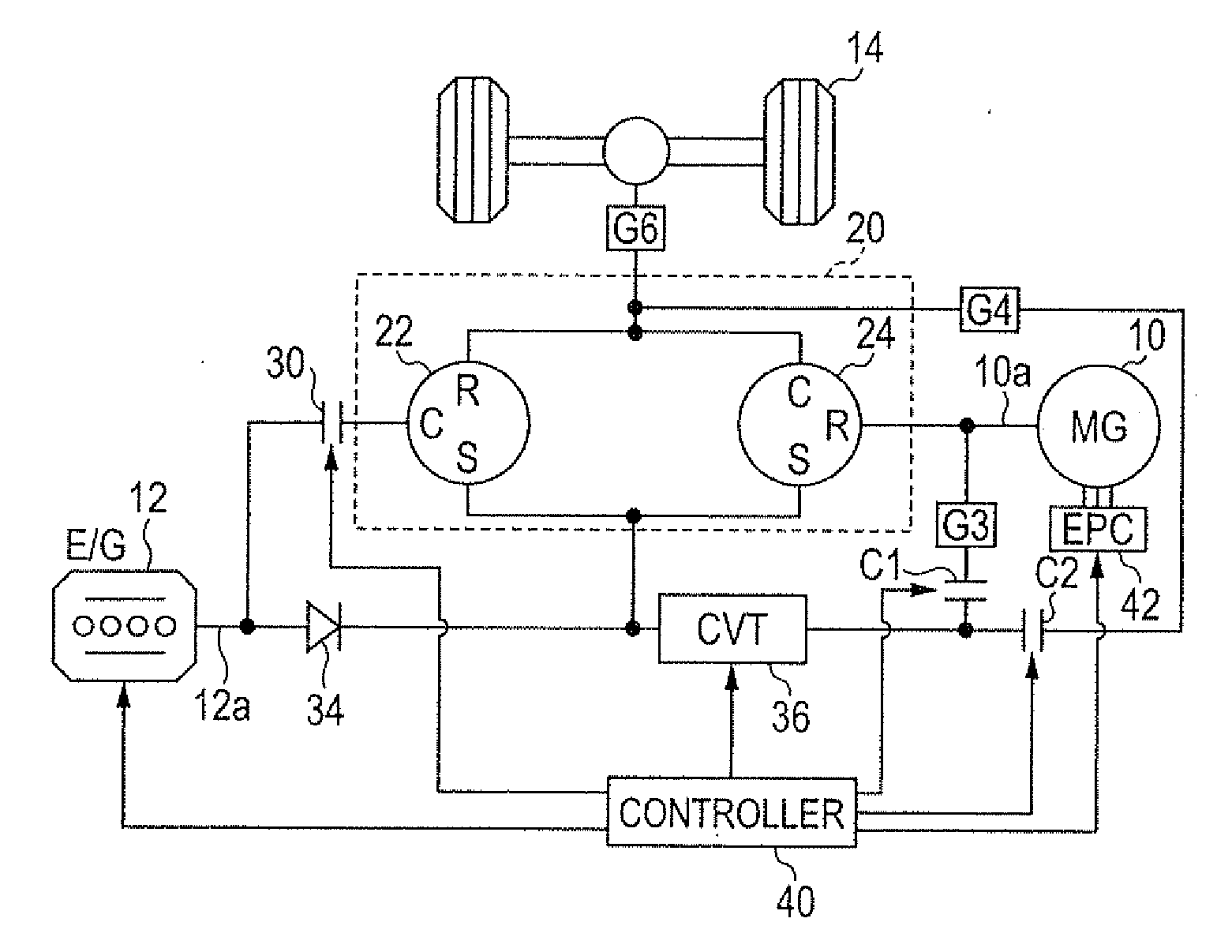
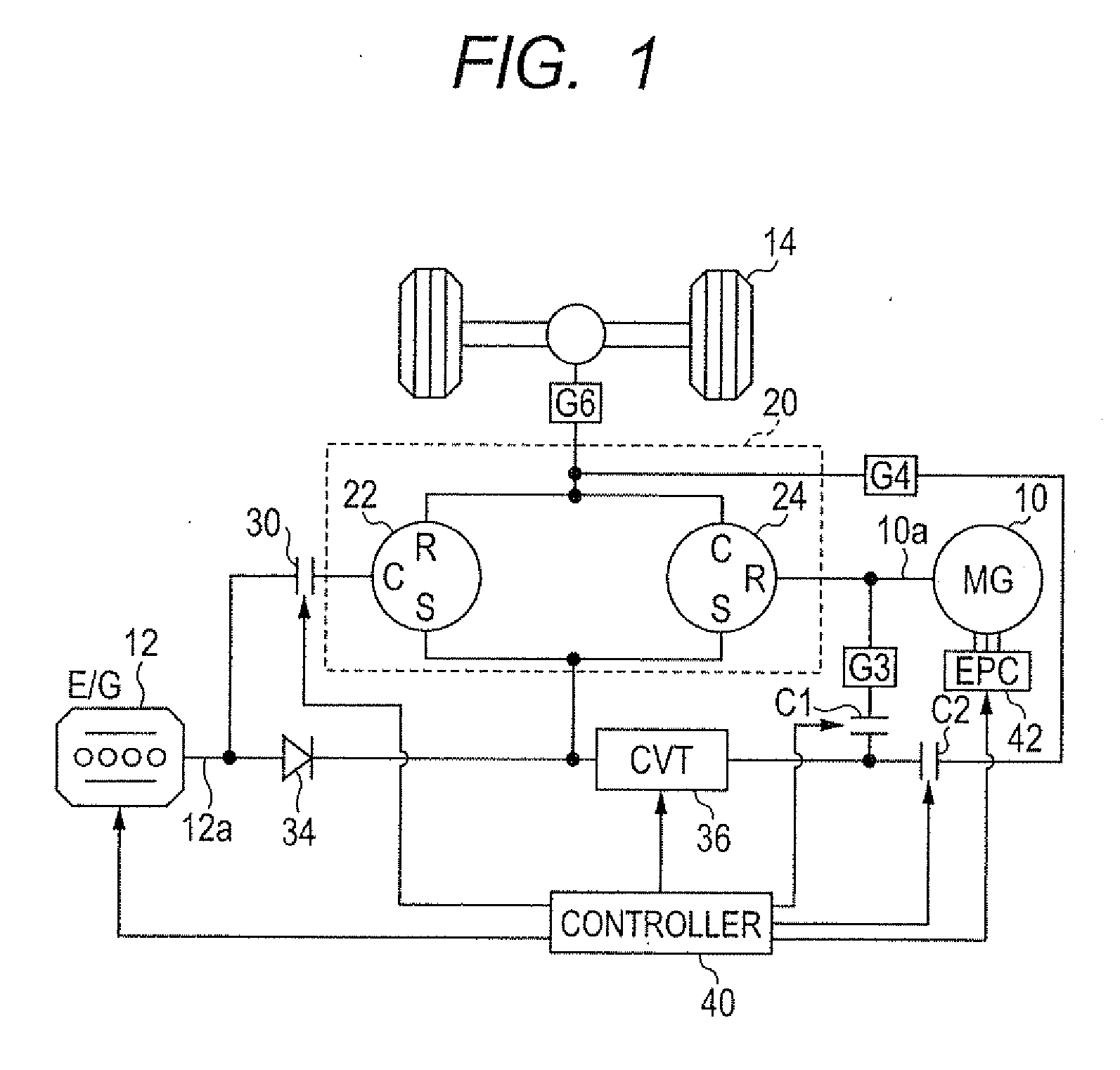
[0081]Referring to the drawings, wherein like reference numbers refer to like parts in several views, particularly to FIG. 1, there is shown a power transmission device according to the invention which is installed in a hybrid system. The hybrid system may be used in the so-called hybrid vehicles.

[0082]The hybrid system includes a motor-generator 10 and a power split device 20. The motor-generator 10 is made of a three-phase ac motor-generator and works as a power producing device or main engine along with an internal combustion engine 12. The power split device 20 works to split power or torque to be outputted among power split rotors disposed therein, in other words, the motor-generator 10, the internal combustion engine (e.g., a gasoline engine) 12, and driven wheels 14 of an automotive vehicle.

[0083]The power split device 20 includes a first planetary gear set 22 and a second planetary gear set 24. The first planetary gear set 22 has a ring gear R joined mechanically to a carrie...

seventh embodiment

[0112]The omission of transmission of torque is eliminated by the gears G3 and G4, as illustrated in FIG. 1. The speeds of the sun gear S, the carrier C, and the ring gear R of the second planetary gear set 24 are all identical with each other or all different from each other. The second planetary gear set 24 of this embodiment is so designed that the speed of the sun gear S is opposite in sign to that of the ring gear R in the nomographic chart. The speeds of the sun gear S, the carrier C, and the ring gear R are, therefore, always different from each other except when they are all zero (0). It is, thus, impossible for only the CVT 36 to realize the condition that the speed of some of the power split rotors to be connected together by the clutch C1 is identical with that of some of the power split rotors to be connected together by the clutch C2. Such realization requires at least one of the gear G3 disposed between the ring gear R of the second planetary gear set 24 and the clutch...

second embodiment

[0127]FIG. 8 illustrates the power transmission system according to the invention. The same reference numbers as employed in FIG. 1 refer to the same parts, and explanation thereof in detail will be omitted here.

[0128]An conditioner 44 (i.e., an vehicle accessory) is installed in the hybrid vehicle and powered by the power split device 20. The air conditioner 44 is equipped with a compressor (not shown) which has a driven shaft connected mechanically to the sun gears S of the first and second planetary gear sets 22 and 24, so that the torque is supplied from the sun gears S to the compressor. The power transmission device is, as described above, capable of rotating the sun gears S of the first and second planetary gear sets 22 and 24 at speeds other than zero (0) when the driven wheels 14 are at rest and thus running the air conditioner 44 when the vehicle is parked.

[0129]The mechanical joint of the air conditioner 44 to the sun gears S of the first and second planetary gear sets 22...


PUM


Abstract

A power transmission device includes a planetary gear set and a first and a second connecting mechanism. The planetary gear set receives power from a power source and outputs it to a power-driven member. The first connecting mechanism connects a first and a second rotor of the planetary gear set through a separate path. The second connecting mechanism connects the second rotor and a third rotor of the planetary gear set through a separate path. The controller is operable selectively in a first operation mode in which the second connecting mechanism is engaged, while the first connecting mechanism is disengaged and a second operation mode in which the second connecting mechanism is engaged, while the first connecting mechanism is disengaged. This ensures suitable mechanical connections among the power source, the power-driven member, and the power split mechanism which match with an operating condition of the power transmission device.

Description

CROSS REFERENCE TO RELATED DOCUMENT[0001]The present application claims the benefits of priority of Japanese Patent Application No. 2009-179547 filed on Jul. 31, 2009, the disclosure of which is incorporated herein by reference.BACKGROUND OF THE INVENTION[0002]1. Technical Field of the Invention[0003]The present invention relates generally to a power transmission device equipped with a plurality of power split rotors which interlock with each other to transmit power or torque from a power source to a power-driven member, and a power transmission system using the same.[0004]2. Background Art[0005]There are known power transmission devices of the above type for use in hybrid vehicles equipped with a power source implemented by an internal combustion engine and an electric motor, and driven wheels to which the power or torque is transmitted from the power source. For example, the power transmission devices, as used in the hybrid vehicles, typically include a planetary gear train consis...

Claims


Application Information

Patent Timeline
IPC IPC(8): F16H37/06F16H3/44F16H48/06B60K6/365B60K6/40B60K6/48B60K6/543B60W10/10B60W20/00F16H3/72F16H37/02
CPCF16H2037/088F16H3/725B60K6/543Y10T74/19023F16H2037/0866F16H37/084Y02T10/6221B60K6/48Y02T10/62
Inventor KAWASAKI, KOJIMATSUE, TAKENORITOKUDOME, YUJI
Owner NIPPON SOKEN
Why Eureka
Try Eureka