Marker delivery device for tissue marker placement

a technology of tissue marker and delivery device, which is applied in the field of medical devices, can solve the problems of inaccurate identification of the location of the biopsy area, and achieve the effect of facilitating complete retraction and facilitating a flexure at the flexible portion

Active Publication Date: 2011-02-03
CR BARD INC
View PDF104 Cites 25 Cited by
  • Summary
  • Abstract
  • Description
  • Claims
  • Application Information

AI Technical Summary

Benefits of technology

[0009]The invention, in another form thereof, is directed to a marker delivery device configured for deploying a tissue marker. The marker delivery device includes a handle configured to be grasped by a user. A cannula has a proximal end and a distal end, the proximal end being coupled to the handle. The cannula is substantially rigid and has a side wall surrounding a lumen that extends along a lengthwise extent of the cannula. The cannula has a flexible portion formed by a slot arrangement having of a plurality of peripheral slots extending through the side wall of the cannula to the lumen. The slots of the plurality of peripheral slots are spaced apart to be substantially parallel along the lengthwise extent of the cannula to facilitate a flexure at the flexible portion of the cannula. A marker introducer rod is movably disposed in the lumen of the cannula to effect a deployment of the tissue marker from the distal end of the cannula. The marker introducer rod has an actuation end and a marker deployment end, and a flexible region that corresponds to the flexible portion of the cannula.
[0010]The invention, in another form thereof, is directed to a marker delivery device configured for deploying a tissue marker. The marker delivery device includes a handle configured to be to be grasped by a user. T...

Problems solved by technology

In some marker delivery devices, the marker may not be completely ejected from the cannula, or may be drawn back into or toward the cannula by the vacuum created upon the withdrawal of the cannula, which results in the marker being moved from the intended site, leading to inaccurate i...

Method used


Image

  • Marker delivery device for tissue marker placement
  • Marker delivery device for tissue marker placement
  • Marker delivery device for tissue marker placement

Examples


Embodiment Construction

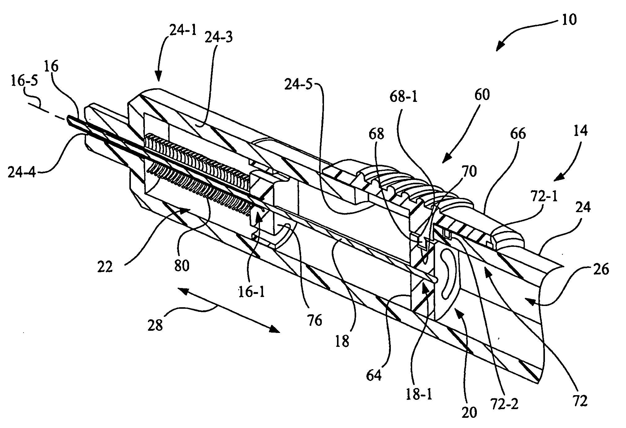
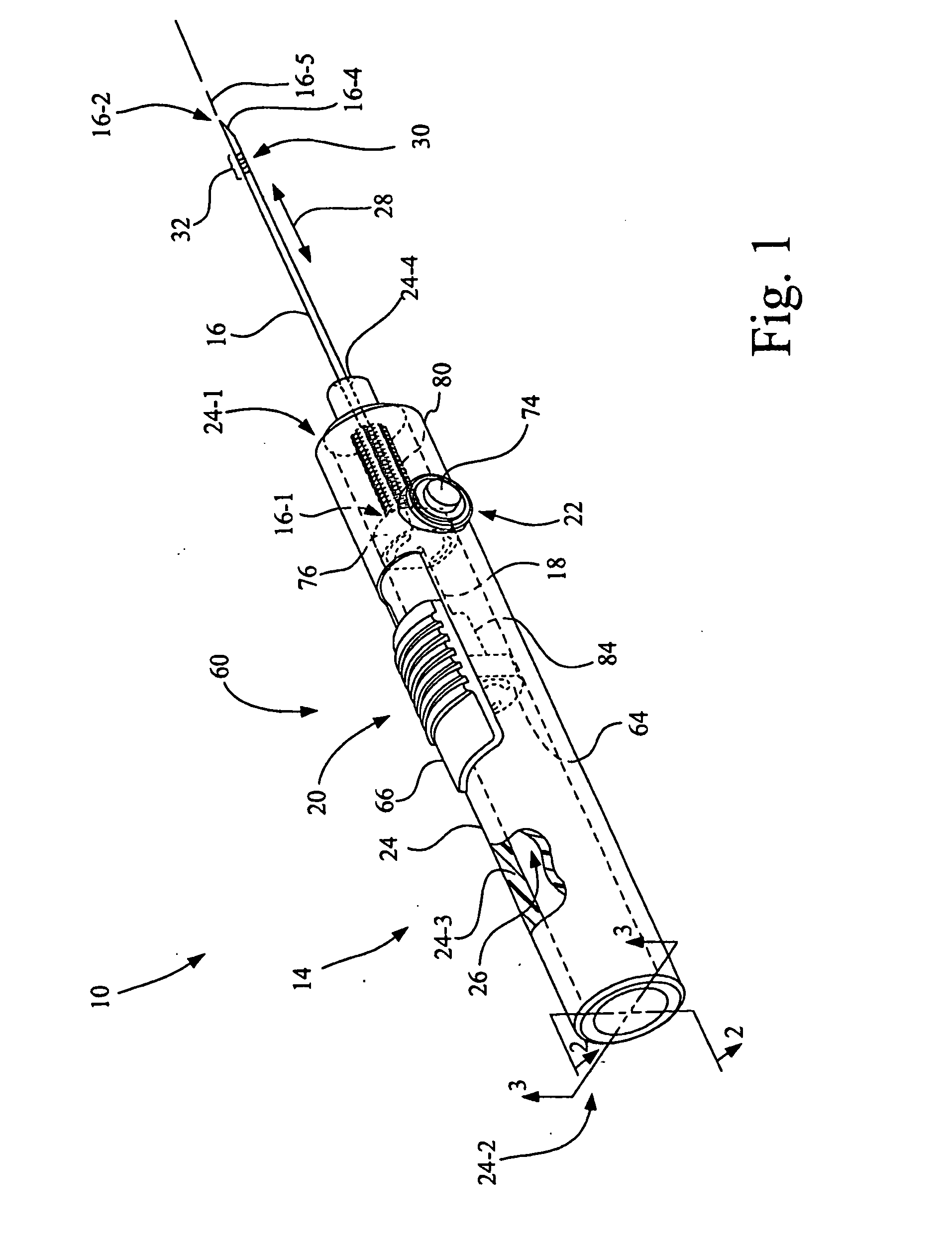
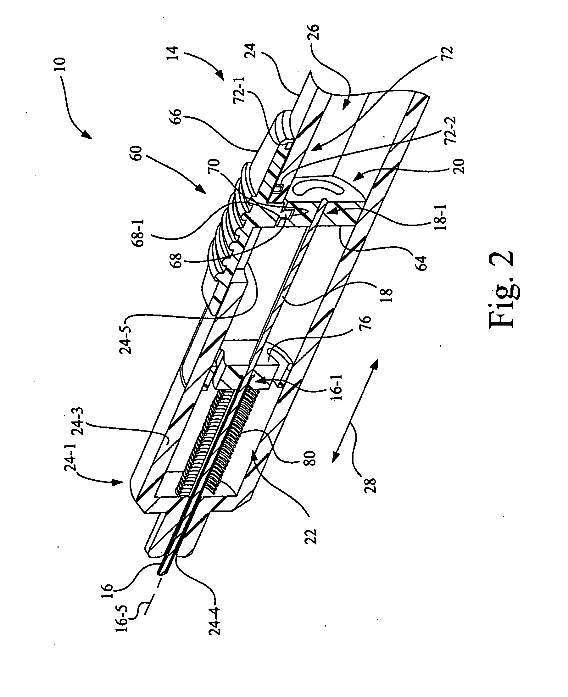
[0030]Referring now to the drawings, and more particularly to FIGS. 1-3, there is shown a marker delivery device 10 configured for deploying a tissue marker 12, in accordance with an embodiment of the present invention.

[0031]Marker delivery device 10 includes a handle 14, a cannula 16, a marker introducer rod 18, a deployment mechanism 20 and a retraction mechanism 22.

[0032]Handle 14 is configured to be grasped by a user, i.e., is of an appropriate size and shape to be grasped by the hand of the user of marker delivery device 10. Handle 14 includes a housing 24 having a front end 24-1, a back end 24-2 and a side wall 24-3, with a longitudinal chamber 26 located between front end 24-1 and back end 24-2 that is surrounded by side wall 24-3. A hole 24-4 leads from chamber 26 through front end 24-1 of housing 24 to the exterior of handle 14. A trigger slot 24-5 extends through side wall 24-3 of housing 24.

[0033]Cannula 16 is configured for holding tissue marker 12 for deployment into a ...


PUM


Abstract

A marker delivery device is configured for deploying a tissue marker. The marker delivery device includes a handle having a chamber, and a cannula. According to one aspect, the cannula has a flexible portion formed by a slot arrangement having of a plurality of spaced-apart substantially parallel peripheral slots extending through the side wall of the cannula to the lumen. A marker introducer rod is movably disposed in the lumen of the cannula for deploying the mark, and has a flexible region that corresponds to the flexible portion of the cannula. According to another aspect, a retraction mechanism is mounted to the handle and is configured to facilitate a complete retraction of both the cannula and the marker introducer rod into the chamber of the housing of the handle upon an actuation of the retraction mechanism.

Description

BACKGROUND OF THE INVENTION[0001]1. Field of the Invention[0002]The present invention relates to medical devices, and, more particularly, to a marker delivery device for percutaneous tissue marker placement.[0003]2. Description of the Related Art[0004]Tissue biopsies are commonly performed on many areas and organs of the human body where it is desirable to ascertain whether or not a lesion or other tissue to be biopsied is cancerous. Often, the lesion or other tissue to be biopsied is identified through use of an imaging technique, such as a computerized axial tomography (CAT) scan, ultrasonography, and mammography.[0005]In breast biopsies, for example, the lesion typically is so small that the biopsy reduces its size to the extent that it is no longer visible by the imaging method employed. In such circumstances, it is desirable to place a tissue marker at the site of the biopsy to enable the medical practitioner subsequently to locate the lesion quickly and accurately in the event...

Claims


Application Information

Patent Timeline
IPC IPC(8): A61B6/00A61M5/315
CPCA61B19/54A61B19/44A61B2019/5487A61B2090/3987A61B90/39
Inventor RANPURA, HIMANSHUVAN LIERE, CHAD C.
Owner CR BARD INC
Why Eureka
Try Eureka