Spinous Process Spacer

a technology of process spacer and spine, which is applied in the field of spine devices, can solve the problems of nerve compression, obesity, depression, general physical deterioration, non-surgical treatment of spinal canal narrowing, etc., and achieve the effect of reducing the risk of neural injury

Active Publication Date: 2011-02-03
LIFE SPINE INC
View PDF36 Cites 8 Cited by
  • Summary
  • Abstract
  • Description
  • Claims
  • Application Information

AI Technical Summary

Benefits of technology

Unlike decompressive surgery / laminectomy, the procedure for implanting the present spinal spacer is completely reversible, leaving all anatomical structures intact. Thus, the implantation procedure for the present spinal spacer can be used as a first line surgical approach without compromising any therapeutic alternatives, including laminectomy.
Because extension (e.g. standing upright) provokes spinal stenosis symptoms, the present spinal spacer is designed to impose what is referred to as acute kyphosis of the lumbar spine. This kyphosing of the vertebral bodies opens the foramen (of which are usually stenotic in the elderly) and allows the nerves to move a little more. Inserted through a small incision, the present spinal spacer is preferably placed posterior to neural structures to minimize the risk of neural injury. Other manners of implantation may be used.
This is a minimally invasive procedure whereby the compressed process spinal spacer is inserted into the space between adjacent bony spinal protrusions to provide localized distraction to the lamina. Once positioned, compressed flanges are expanded to provide an “X” shaped body. Legs of the X-shaped body allow receipt of the bony spinal protrusions.

Problems solved by technology

Such degenerative or age-related changes in our bodies can lead to compression of nerves (i.e. pressure on the nerves that can cause pain and / or damage).
Lack of activity because of lumbar spinal stenosis may lead to obesity, depression and general physical deterioration.
Such non-surgical treatments do not correct the spinal canal narrowing of lumbar spinal stenosis itself but may provide long-lasting pain control and improved life function without requiring a more invasive treatment.

Method used


Image

  • Spinous Process Spacer
  • Spinous Process Spacer
  • Spinous Process Spacer

Examples


Embodiment Construction

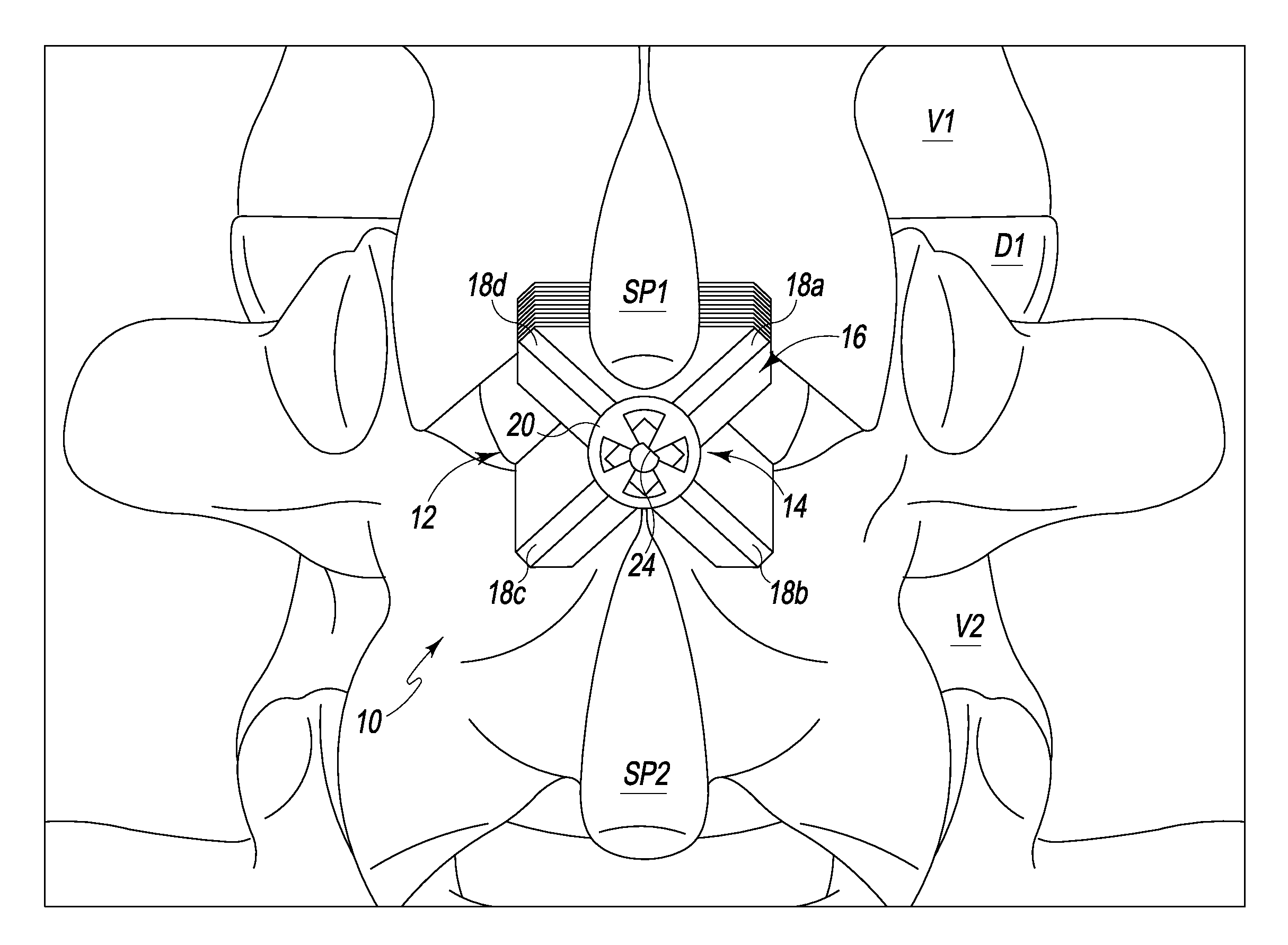
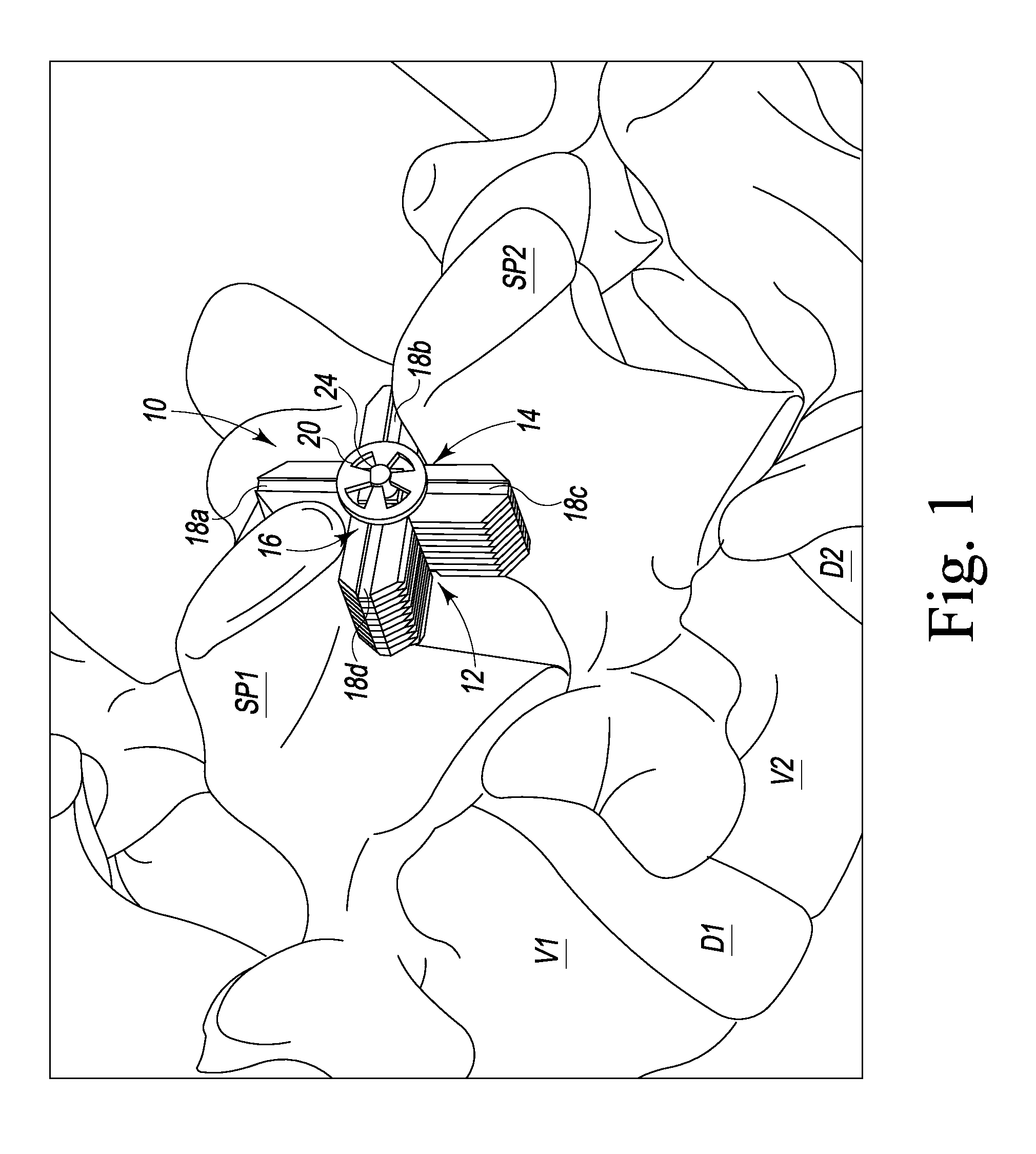
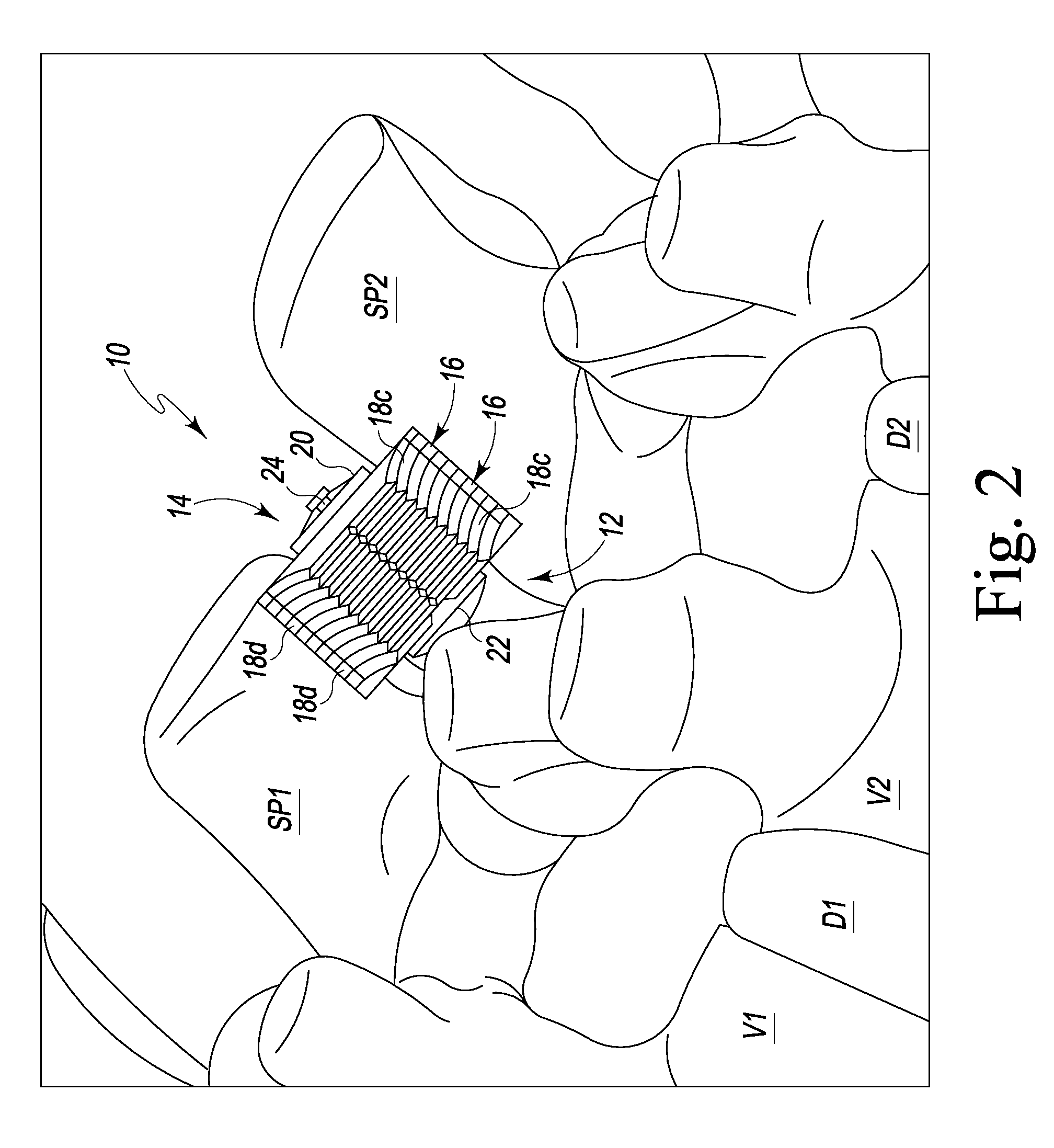
FIGS. 1 through 3 depict a portion of a human spine wherein a spinous process spacer 10, fashioned in accordance with the present principles, has been implanted between bony protrusions of adjacent vertebrae. Particularly, there is depicted adjacent vertebra V1 and V2 of a portion of the spine, with a spine disc D1 situated between the vertebrae. Vertebra V1 has a spinous process SP1 and vertebra V2 has a spinous process SP2. The spinous process spacer 10 is shown situated between the spinous processes SP1 and SP2 of respective adjacent vertebrae V1 and V2 in the expanded position. It should be appreciated that while the present spinal process spacer 10 is shown situated between spinal processes SP1 and SP2, the present spinal process spacer 10 may be used as an interlaminar, interbody, or interbony spinal protrusion spacer. As such, while the present spinal process spacer 10 is shown and described in relation to the spinal processes of adjacent vertebrae, the spinal process spacer ...


PUM


Abstract

A spinous process spacer that is designed to maintain a desired spatial relationship between adjacent vertebrae, is configured for introduction into a spinal implant site in a compressed state and then expands in situ. Once expanded, formations of the present spinal spacer form areas, pockets or spaces that receive at least one bony portion of each adjacent vertebra. The present spinous process spacer has a changeable circumferential profile wherein a first circumferential profile is smaller than a second circumferential profile in order to provide/achieve its compressed and expanded states. The first circumferential profile defines the collapsed position or state while the second circumferential profile defines the position or state. Upon implantation, the present spinous process spacer is not fixed to any bony structure of the vertebrae but provides support. In this regard, use of the spinous process spacer, by itself, will not result in vertebral fusion. However, fusion can result with the use of bone graft packed about the spinous processes (and the spinous process spacer) or in conjunction with the use of an intervertebral body spacer.

Description

BACKGROUND OF THE INVENTION1. Field of the InventionThe present invention relates to devices for the spine and, more particularly, to a spinal implant for the treatment of stenotic spinal bone.2. Background InformationAs we age various changes can occur in the body. For instance, the ligaments of the spine can thicken and calcify (i.e. harden from deposits of calcium), bone and joints may enlarge, bone spurs called osteophytes may form, spinal discs may collapse and bulge (i.e. herniate) or one vertebra may slip over another (spondylolisthesis). Any one or these conditions and / or others can cause what is known as lumbar spinal stenosis. Lumbar spinal stenosis is a narrowing of the bony spinal canal. While some people are born with this condition, most often spinal stenosis is the result of one of the above-identified degenerative conditions that develop in mainly the middle-aged and elderly population.In this regard, spinal stenosis may be considered as the gradual result of aging a...

Claims


Application Information

Patent Timeline
Patent Type & Authority Applications(United States)
IPC IPC(8): A61B17/70
CPCA61F2002/30179A61B17/7065
Inventor HARTSELL, BRIAN D.BUCCI, KARA A.
Owner LIFE SPINE INC
Why Eureka
Try Eureka