Apparatus and Method for Controlling Communications to and from Utility Service Points

a technology of communication and service point, applied in the field of electric power supply and generation system, can solve the problems of uncontrollable pets, no techniques for calculating power consumption and/or greenhouse gas emissions, and physical difficulty in gaining access to the meter

Active Publication Date: 2011-02-03
LANDISGYR INNOVATIONS INC +1
View PDF110 Cites 181 Cited by
  • Summary
  • Abstract
  • Description
  • Claims
  • Application Information

AI Technical Summary

Problems solved by technology

However, no techniques exist for calculating power consumption and / or greenhouse gas emissions (e.g., carbon gas emissions, sulfur dioxide (SO2) gas emissions, and / or nitrogen dioxide (NO2) emissions), and reporting the state of a particular power consuming device or set of power consuming devices operating under the control of a two-way positive control load management policy.
On-site meter reading has a number of disadvantages, including (a) dangers to utility personnel from uncontrolled pets or other animals, (b) physical difficulties gaining access to the meter, (c) weather, and (d) time and cost associated with traveling to a service point, which may be in a remote area.
However, because AMR typically requires a utility worker to be in the proximity of each service point in order to read the service point's meter, the labor costs associated with implementing AMR are still substantial.
Depending on the available bandwidth of the WAN's reverse link from the smart meters 211-215 to the utility 207, a substantial number of simultaneous or overlapping transmissions from the smart meters 211-215 can place an inordinate strain on the WAN 217 and cause a data bottleneck, possibly resulting in lost or unacceptably latent (e.g., out-of-date) data.

Method used


Image

  • Apparatus and Method for Controlling Communications to and from Utility Service Points
  • Apparatus and Method for Controlling Communications to and from Utility Service Points
  • Apparatus and Method for Controlling Communications to and from Utility Service Points

Examples


Embodiment Construction

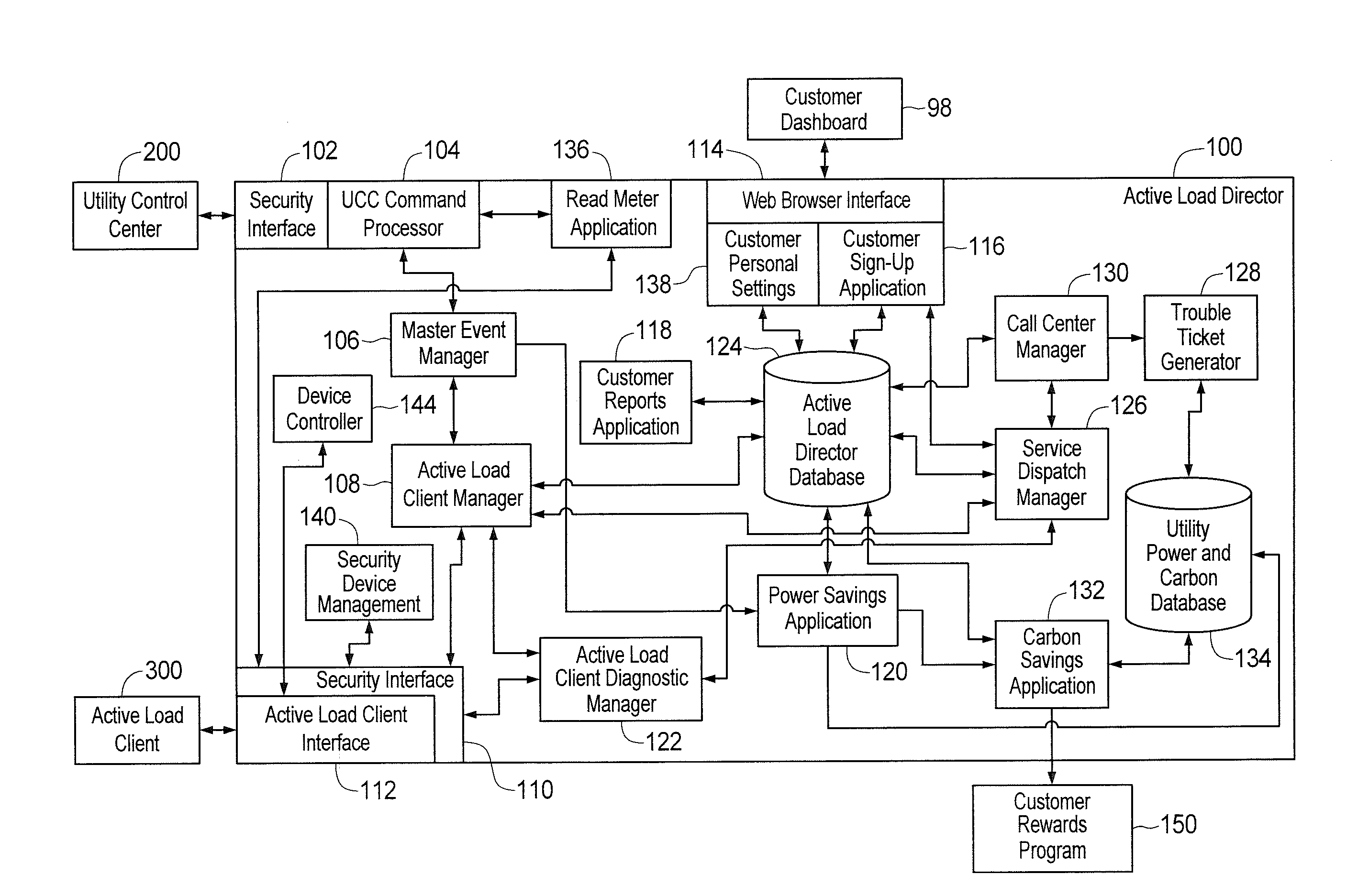
[0026]Before describing in detail exemplary embodiments that are in accordance with the present invention, it should be observed that the embodiments reside primarily in combinations of apparatus components and processing steps related to controlling transmission of messages over fixed bandwidth communication links between a central controller, such as an active load director, and a plurality of fixed position and immobile communication devices, such as active load client devices, in an active load management system. Accordingly, the apparatus and method components have been represented where appropriate by conventional symbols in the drawings, showing only those specific details that are pertinent to understanding the embodiments of the present invention so as not to obscure the disclosure with details that will be readily apparent to those of ordinary skill in the art having the benefit of the description herein.

[0027]In this document, relational terms, such as “first” and “second...


PUM


Abstract

An apparatus and method control transmission of messages over a fixed bandwidth link from fixed position communication devices to a central controller in a load management system. The messages include information relating to electric power consumption by power consuming devices located at service points that include the communication devices. In one embodiment, the central controller determines an identifier associated with each communication device, a reporting period during which the messages are to be transmitted by the communication devices, and transmission increments within the reporting period. The controller allocates each transmission increment to a respective group of communication devices. The controller then determines a transmission time for a message from a particular communication device based on the identifier for the particular device, a duration of a transmission increment allocated to a group of communication devices that includes the particular device, and a quantity of communication devices in the particular device's group.

Description

CROSS REFERENCE TO RELATED APPLICATIONS[0001]This application is a continuation-in-part of co-pending U.S. application Ser. No. 12 / 715,124 filed on Mar. 1, 2010, which is a division of U.S. application Ser. No. 11 / 895,909 filed on Aug. 28, 2007, now U.S. Pat. No. 7,715,951 B2, and is incorporated herein by this reference as if fully set forth herein. This application is also a continuation-in-part of co-pending U.S. application Ser. No. 12 / 715,195 filed on Mar. 1, 2010, which is also a division of U.S. application Ser. No. 11 / 895,909, now U.S. Pat. No. 7,715,951 B2, and is incorporated herein by this reference as if fully set forth herein. This application further claims priority under 35 U.S.C. §119(e) upon U.S. Provisional Application Ser. No. 61 / 278,669 filed on Oct. 9, 2009 solely to the extent of the subject matter disclosed in said provisional application, which application is incorporated herein by this reference as if fully set forth herein. Finally, this application is rela...

Claims


Application Information

Patent Timeline
Patent Type & Authority Applications(United States)
IPC IPC(8): G06F15/173
CPCG06Q10/00G01D4/004G06Q50/06H04B3/54G01D4/002Y02B90/242Y04S20/322G08C15/06H04B2203/5433H04L12/16H04L12/10Y02B90/20Y04S20/30
Inventor FORBES, JR., JOSEPH W.WEBB, JOEL L.LONG, JOHN O. F.
Owner LANDISGYR INNOVATIONS INC
Why Eureka
Try Eureka