Electronic control apparatus including electrically rewritable non-volatile memory
- Summary
- Abstract
- Description
- Claims
- Application Information
AI Technical Summary
Benefits of technology
Problems solved by technology
Method used
Image

Examples
first embodiment
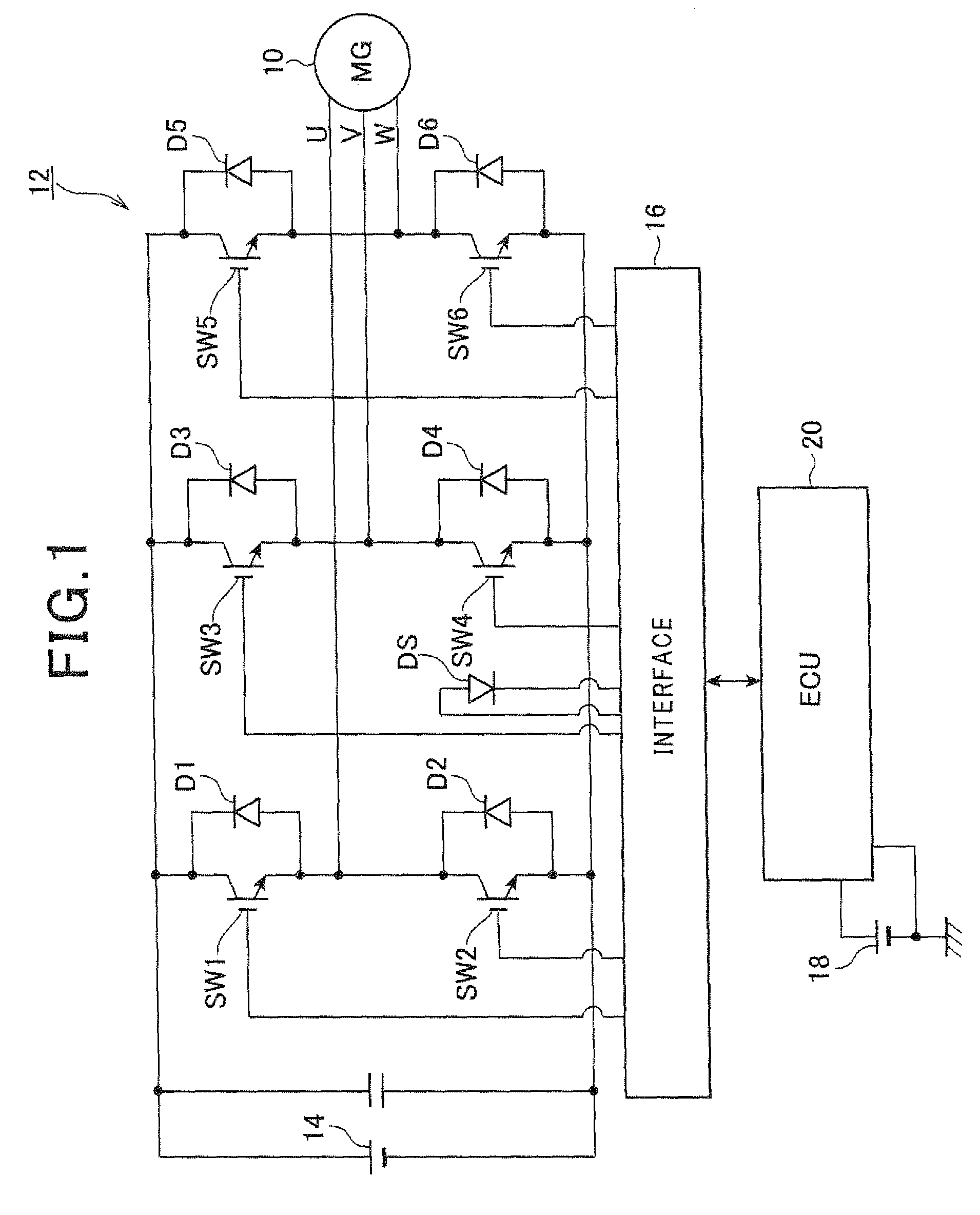
[0022]FIG. 1 is a diagram showing the structure of a control system for a hybrid vehicle including an ECU as an electronic control apparatus according to a first embodiment of the invention.
[0023]As shown in FIG. 1, the three phases (the U-phase, V-phase and W-phase) of a motor generator 10 are connected to an inverter 12. The inverter 12, which is a three-phase inverter, applies the voltage of a high-voltage battery 14 to the three phases of the motor generator 10 in an appropriate manner. In more detail, the inverter 12 is constituted of a series connection of switching elements SW1 and SW2, a series connection of switching elements SW3 and SW4, and a series connection of switching elements SW5 and SW6, which are operated to connect each of the three phases of the motor generator 10 to the positive or negative terminal of the high voltage battery 14. The connection node between the switching elements SW1 and SW2 is connected to the U-phase of the motor generator 10. The connection...
second embodiment
[0046]Next, a second embodiment of the invention is described with particular emphasis on the difference with the first embodiment.
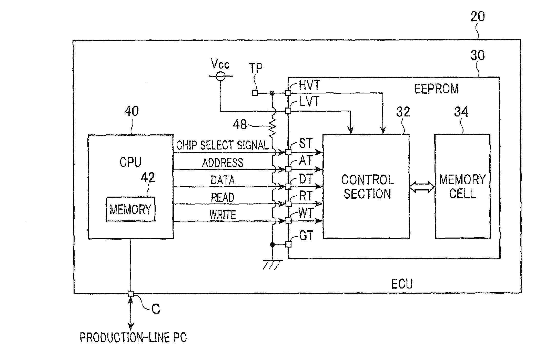
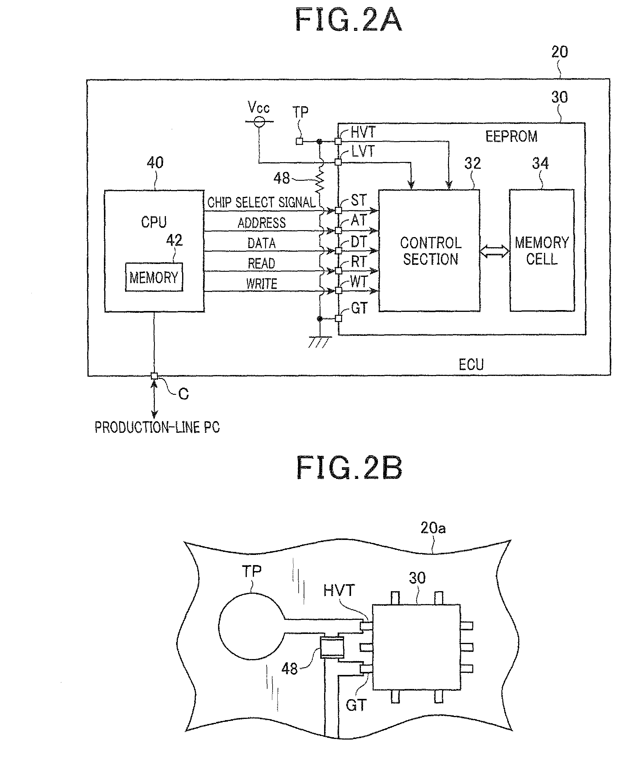
[0047]FIG. 5 is a diagram showing a part of the internal structure of the ECU 20 of this embodiment, the part being mainly for storing the learned results. In FIG. 5, the reference numerals identical to those shown in FIG. 2 represent the same elements.
[0048]As shown in FIG. 5, in this embodiment, the means to fix the voltage of the high voltage terminal HVT is constituted including the low voltage terminal LVT. In more detail, the low voltage terminal LVT and the high voltage terminal HVT are connected to each other through a diode 50 whose forward direction is from the low voltage terminal LVT to the high voltage terminal HVT. This configuration makes it possible to fix the voltage of the high voltage terminal HVT using the low voltage terminal LVT, and to prevent the low voltage terminal LVT from being applied with the high voltage at the time of appl...
third embodiment
[0051]Next, a third embodiment of the invention is described with particular emphasis on the difference with the second embodiment.
[0052]FIG. 6 is a diagram showing a part of the internal structure of the ECU 20 of this embodiment, the part being mainly for storing the learned results. In FIG. 6, the reference numerals identical to those shown in FIG. 5 represent the same elements.
[0053]As shown in FIG. 6, in this embodiment, a resistor 52 is connected between the high voltage terminal HVT and the low voltage terminal LVT. It is preferable that the resistance of the resistor 52 is as large as possible in order to reduce the power consumed by the resistor 52 while the test point TP is applied with the high voltage.
[0054]The third embodiment provides the similar advantages as the advantages (1), (2), (4) and (5) provided by the first embodiment, and the advantage (6) provided by the second embodiment.
[0055]It is a matter of course that various modifications can be made to the above em...
PUM
 Abstract
Description
Claims
Application Information
 - R&D
- Intellectual Property
- Life Sciences
- Materials
- Tech Scout
- Unparalleled Data Quality
- Higher Quality Content
- 60% Fewer Hallucinations
Browse by: Latest US Patents, China's latest patents, Technical Efficacy Thesaurus, Application Domain, Technology Topic, Popular Technical Reports.
© 2025 PatSnap. All rights reserved.Legal|Privacy policy|Modern Slavery Act Transparency Statement|Sitemap|About US| Contact US: help@patsnap.com