
Control server and display screen control system of multi-functional peripheral

a control server and peripheral technology, applied in the direction of digital computers, instruments, computing, etc., can solve problems such as user forgetfulness

Inactive Publication Date: 2011-02-03
SHARP KK
View PDF8 Cites 12 Cited by
  • Summary
  • Abstract
  • Description
  • Claims
  • Application Information

AI Technical Summary

Benefits of technology

[0008]An object of the present invention is to provide a display screen control system and a control server for preventing a user from unconsciously using a pay application in the display screen control system of a multi-functional peripheral composed of a multi-functional peripheral including a display portion for executing a function of an application stored in a application server and a control server that transmits control information for displaying an initial screen based on a usage (selection) history of a function of a user on the display portion of the multi-functional peripheral.

Problems solved by technology

That is, there has been such a problem that a user forgets to be charged and uses a pay application frequently when a setting screen of a function of the pay application that is selected before is displayed as an initial screen immediately after login.
Further, recently, there has been a display screen control system of a multi-functional peripheral that controls an initial screen for each login user displayed by the multi-functional peripheral based on the control information from a control server connected to the multi-functional peripheral, and the above-described problem may occur similarly when the technology disclosed in Japanese Laid-Open Patent Publication No. 2008-273126 is applied to this system.

Method used


Image

  • Control server and display screen control system of multi-functional peripheral
  • Control server and display screen control system of multi-functional peripheral
  • Control server and display screen control system of multi-functional peripheral

Examples


Embodiment Construction

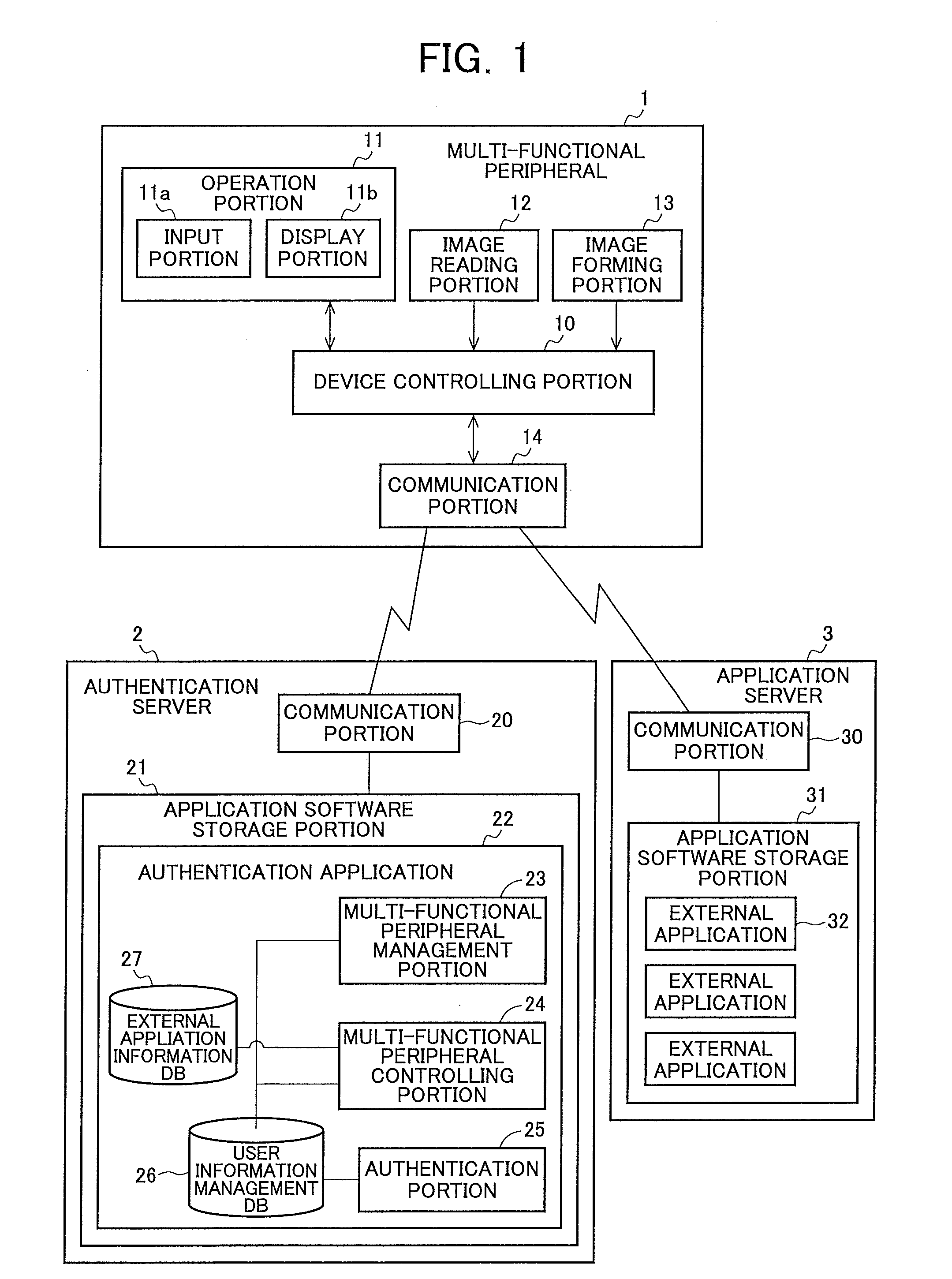
[0029]FIG. 1 is a block diagram illustrating a schematic configuration example of a display control system of a multi-functional peripheral of the present invention. The display control system shown in FIG. 1 is provided with a multi-functional peripheral 1, an authentication server 2 and an application server (external application server) 3.

[0030]The multi-functional peripheral 1 is a digital multi-functional peripheral or an analogue multi-functional peripheral, and is provided with a device controlling portion 10, an operation portion 11, an image reading portion 12, an image forming portion 13 and a communication portion 14. The device controlling portion 10 controls each portion provided in the multi-functional peripheral 1. The operation portion 11 has an input portion 11a and a display portion 11b such as a liquid crystal display (LCD). The input portion 11a has various input key groups and a touch panel for accepting user input provided in the display portion 11b.

[0031]The ...


PUM


Abstract

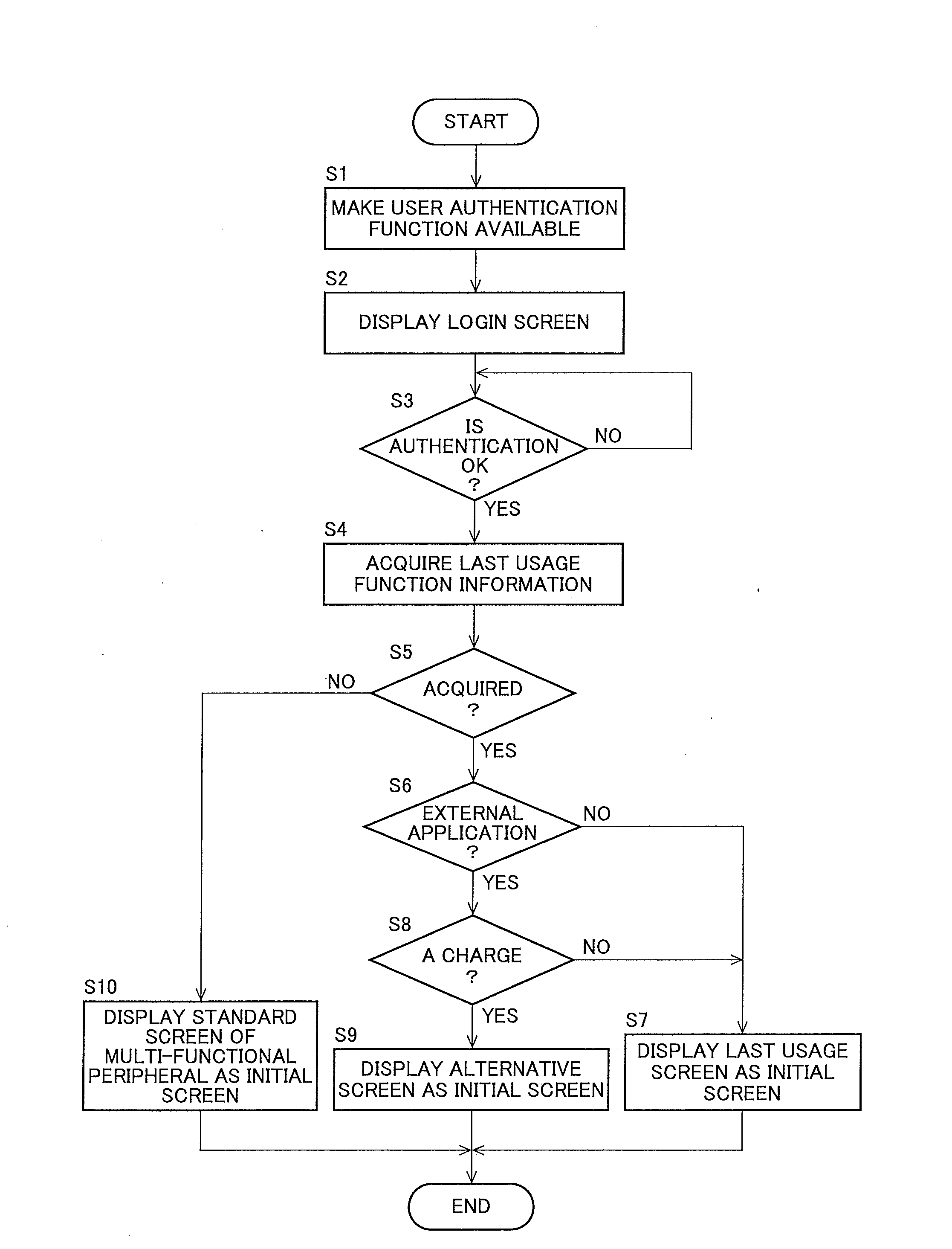
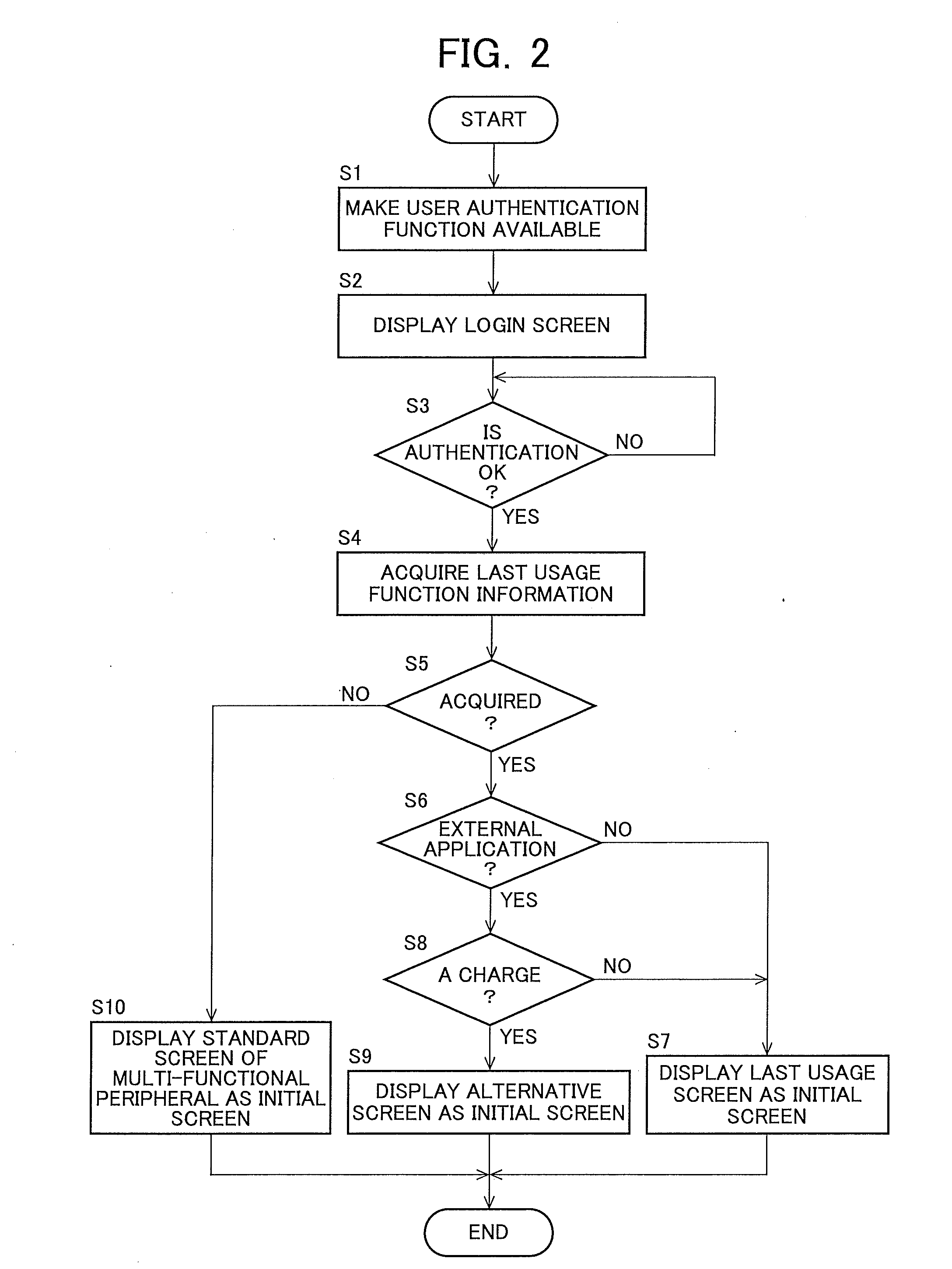
An initial screen is displayed on the display portion of a multi-functional peripheral based on a usage history of a user to secure convenience of the user and the user is prevented from unconsciously using a charged application. An authentication server stores usage history information of function of a multi-functional peripheral capable of executing a function of an external application for each user, stores usage fee information of the external application, extracts a predetermined function out of functions used by a user based on information of the user who logs in the multi-functional peripheral, transmits control information for displaying a screen of the function to the multi-functional peripheral in the case where the predetermined function is free, and transmits the control information for displaying a predetermined alternative screen in stead of the screen of the function to the multi-functional peripheral in the case where the predetermined function is charged.

Description

CROSS-NOTING PARAGRAPH[0001]This non-provisional application claims priority under 35 U.S.C. §119(a) on Patent Application No. 2009-180674 filed in JAPAN on Aug. 3, 2009, the entire contents of which are hereby incorporated herein by reference.FIELD OF THE INVENTION[0002]The present invention relates to a display screen control system of a multi-functional peripheral composed of an application server storing an application, a multi-functional peripheral including a display portion for executing a function of the above-described application and a control server generating control information for displaying an initial screen of each user on the display portion of the multi-functional peripheral to transmit to the multi-functional peripheral, and the above-described control server.BACKGROUND OF THE INVENTION[0003]In a conventional multi-functional peripheral, a default screen (copy screen, etc.) to be designated by a setting of the multi-functional peripheral is displayed as an initial...

Claims


Application Information

Patent Timeline
IPC IPC(8): G06F3/00
CPCH04N1/00222H04N1/00244H04N1/00408H04N2201/3273H04N2201/0072H04N2201/3205H04N2201/3245H04N2201/001
Inventor TSUJIMOTO, KUNIHIKO
Owner SHARP KK
Learn More