Seat belt retractor torsion rod activity sensor

a technology of activity sensor and seat belt, which is applied in the direction of instruments, pedestrian/occupant safety arrangements, force/torque/work measurement apparatus, etc., can solve the problems of airbag replacement, obvious need for replacement, and risk of airbag deploymen

Inactive Publication Date: 2005-07-12
KEY SAFETY SYST
View PDF12 Cites 32 Cited by
  • Summary
  • Abstract
  • Description
  • Claims
  • Application Information

AI Technical Summary

Benefits of technology

[0008]The seat belt load limiter of this invention employs a magnetostrictive sensor that detects the elastic loading and plastic deformation of a torsion rod forming part of a seat belt retractor. In the seat belt load limiter a magnet and a coil are placed about or adjacent to a load limiting torsion rod forming part of a seat belt retractor. When the torsion rod undergoes the elastic or plastic strain, an electrical voltage is induced in the coil that is used to detect elastic or plastic strain of the torsion rod. Magnetostrictive sensors have the potential of being reliable and of operating over a large temperature range making them suitable for use in motor vehicle applications.
[0012]It is yet another feature of the present invention to provide a seat belt load limiter which can provide black box data by means of a magnetostrictive or inverse magnetostrictive principle for analysis after a motor vehicle crash.

Problems solved by technology

In a less severe crash, the airbags typically will not deploy, as deployment of airbags means the airbags must be replaced at some considerable expense and there is some risk associated with airbag deployment.
On the other hand, if the airbag has deployed it is in obvious need of replacement.
However, once the seat belt spool is locked, significant further payout of the seat belt results in shearing of the load limiting torsion rod.
If the seat belt is fastened but not about the occupant the motor vehicle safety system may not respond correctly unless a way can be found to determine that although the seat belt is fastened it is not operating to restrain an occupant.

Method used


Image

  • Seat belt retractor torsion rod activity sensor
  • Seat belt retractor torsion rod activity sensor
  • Seat belt retractor torsion rod activity sensor

Examples


Embodiment Construction

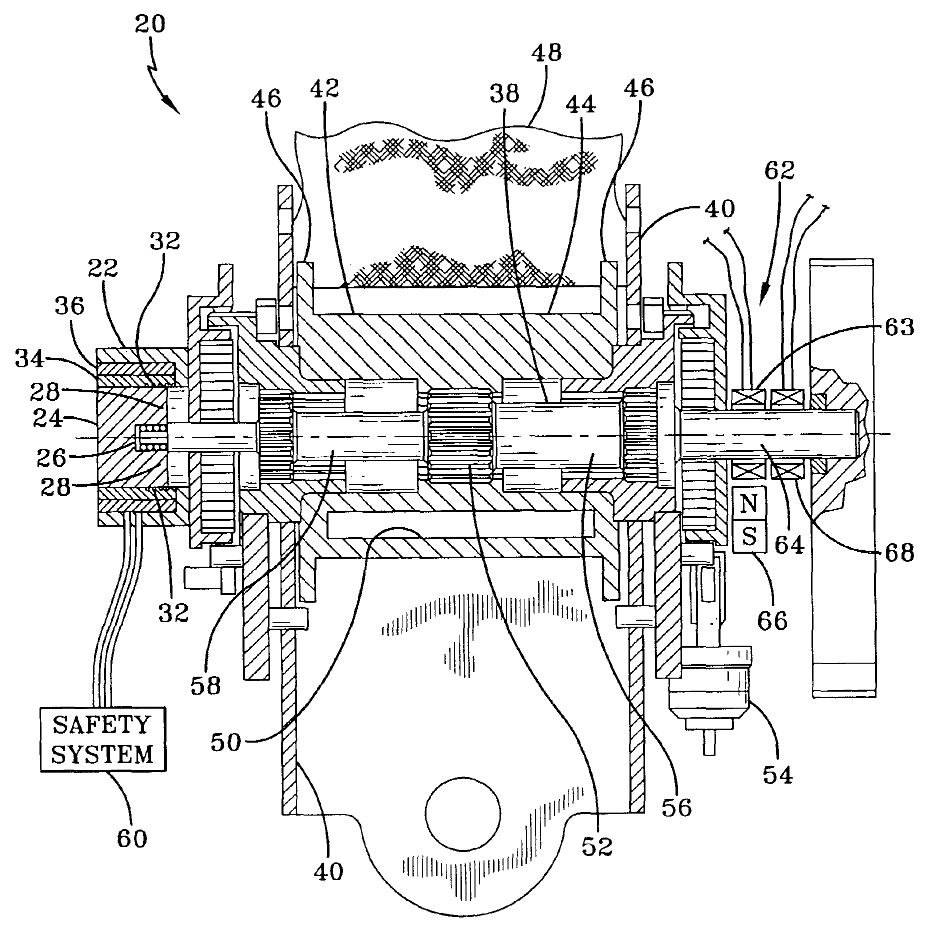
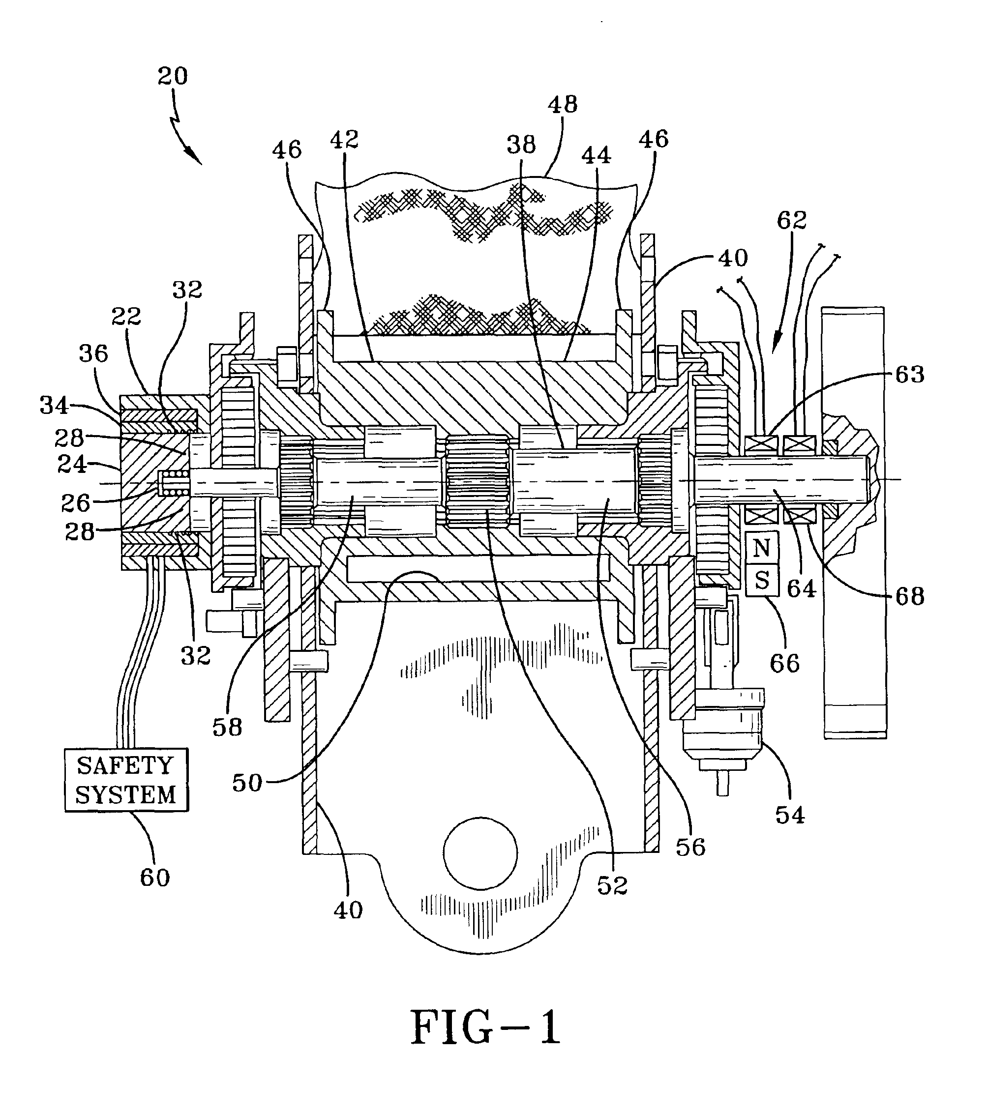
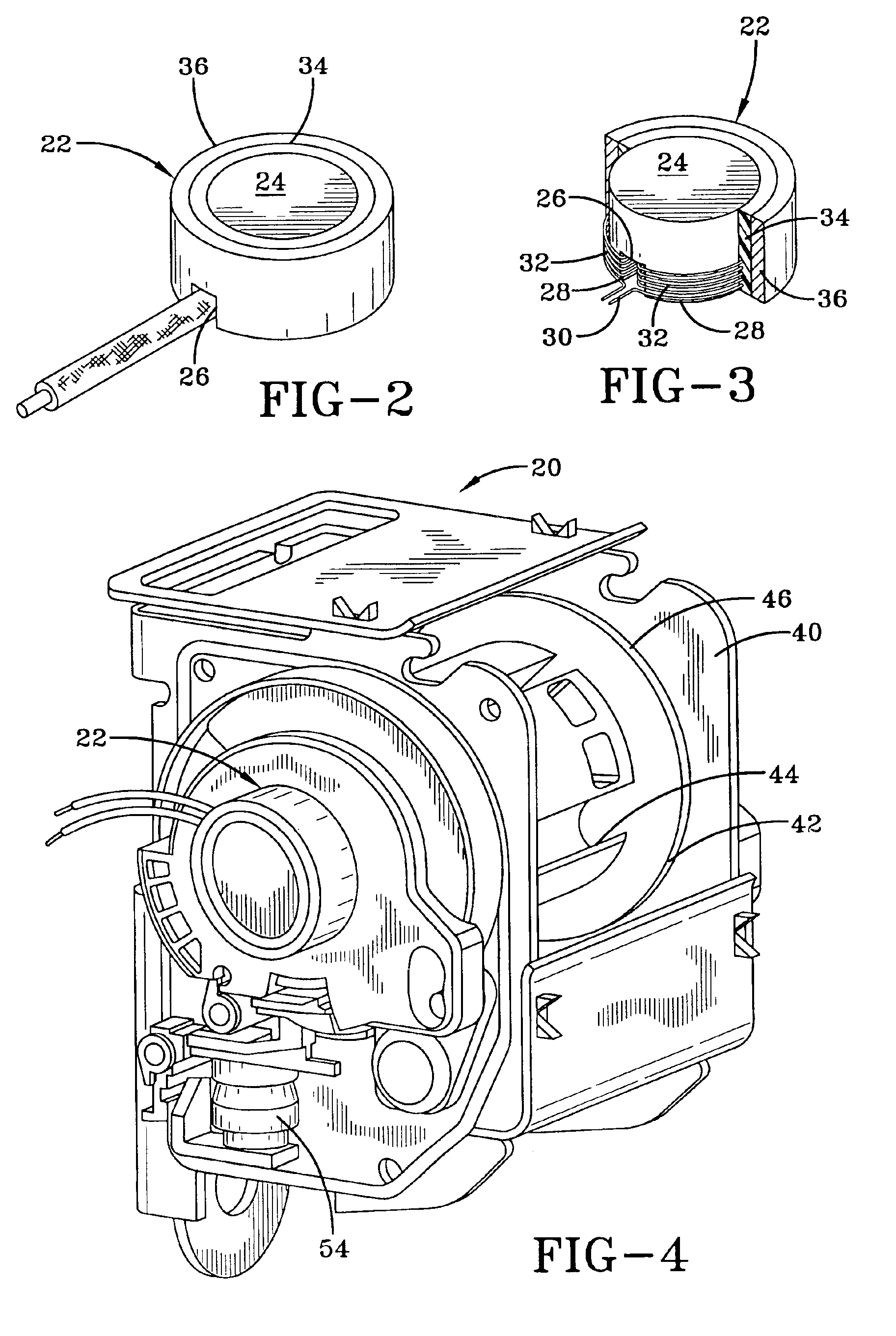
[0018]Referring more particularly to FIGS. 1-4, wherein like numbers refer to similar parts, a seat belt retractor 20 incorporating a load limiter in the from of a yielding torsion rod 38 is shown FIG. 1. The seat belt retractor 20 is similar to the seat belt retractor shown in U.S. Pat. No. 6,012,667, however the seat belt retractor 20 has been modified by the addition of a magnetostrictive sensor 22. The magnetostrictive sensor 22 is shown in more detail in FIGS. 2 and 3. The magnetostrictive sensor 22 has a cylindrical biasing magnet 24 which has a slot 26 which extends through the biasing magnet 24 and which forms two legs 28 about which a wire 30 is wound to form two coils 32. The biasing magnet 24 and the wire 30 forming the coils 32 are surrounded by an epoxy layer 34 which in turn is surrounded by a stainless steel case 36.

[0019]The magnetostrictive effect was first reported by Joule in 1847. The magnetostrictive effect describes a small change in physical dimensions of ferr...


PUM

PropertyMeasurementUnit
magnetostrictiveaaaaaaaaaa
energyaaaaaaaaaa
plastic yieldingaaaaaaaaaa

Abstract

A seat belt load limiter employs a magnetostrictive sensor to detect the elastic loading and plastic deformation of a torsion rod forming part of a seat belt retractor. A magnet and a coil are placed about or adjacent to the torsion rod. When the torsion rod undergoes elastic or plastic strain, an electrical voltage is induced in the coil which is used to detect elastic or plastic strain of the torsion rod. A vehicle safety system uses the output of the magnetostrictive sensor to inform the vehicle operator when the seat belt load limiter is in need of replacement. The output of the magnetostrictive sensor as processed by the vehicle safety system can also be used to detect a situation where the seat occupant is not restrained by the seat belt and to make an airbag deployment decision.

Description

FIELD OF THE INVENTION[0001]The present invention relates to seat belt retractors with load limiting structures and sensors for monitoring their operation.BACKGROUND OF THE INVENTION[0002]The benefit of seat belts in preventing or limiting injury during a motor vehicle crash is substantially enhanced if a system to detect the onset of a crash is used in combination with a device known as a seat belt retractor which tightens the seat belt in response to the detection of a crash of a selected severity. The reeling of the belt onto the belt spool is termed “retraction,” while the unwinding of belt is known as “protraction.” Further benefit is derived from using a seat belt spool which incorporates a load limiting torsion rod, the load limiting torsion rod allows seat belt webbing to be drawn from the seat belt spool under load to absorb energy from a vehicle occupant restrained by the seat belt. The load limiting mechanism is brought into operation by a level of load applied to the bel...

Claims


Application Information

Patent Timeline
Patent Type & Authority Patents(United States)
IPC IPC(8): B60R22/46B60R22/00B60R22/48G01L5/10
CPCB60R22/4676G01L5/103B60R2022/469B60R22/28B60R22/34B65H75/48B60R22/00
Inventor CLANCY, III, EDWARD W.KELLER, GERALD J.BLACKBURN, BRIAN
Owner KEY SAFETY SYST
Why Eureka
Try Eureka