Combustor tile mounting arrangement

a technology for mounting arrangements and tiles, applied in the field of tiles, can solve the problem of line of sight process for laser machining

Active Publication Date: 2011-02-10
ROLLS ROYCE PLC
View PDF16 Cites 53 Cited by
  • Summary
  • Abstract
  • Description
  • Claims
  • Application Information

AI Technical Summary

Benefits of technology

[0015]Preferably, the tile body has one or more spacing projections (such as one or more rails extending along the perimeter of the tile body) protruding from the cold side thereof, the spacing projections engaging with the hot side of the combustor wall when the tile is fastened thereto to determine a spacing

Problems solved by technology

However, this presents a problem in that l

Method used


Image

  • Combustor tile mounting arrangement
  • Combustor tile mounting arrangement
  • Combustor tile mounting arrangement

Examples


first embodiment

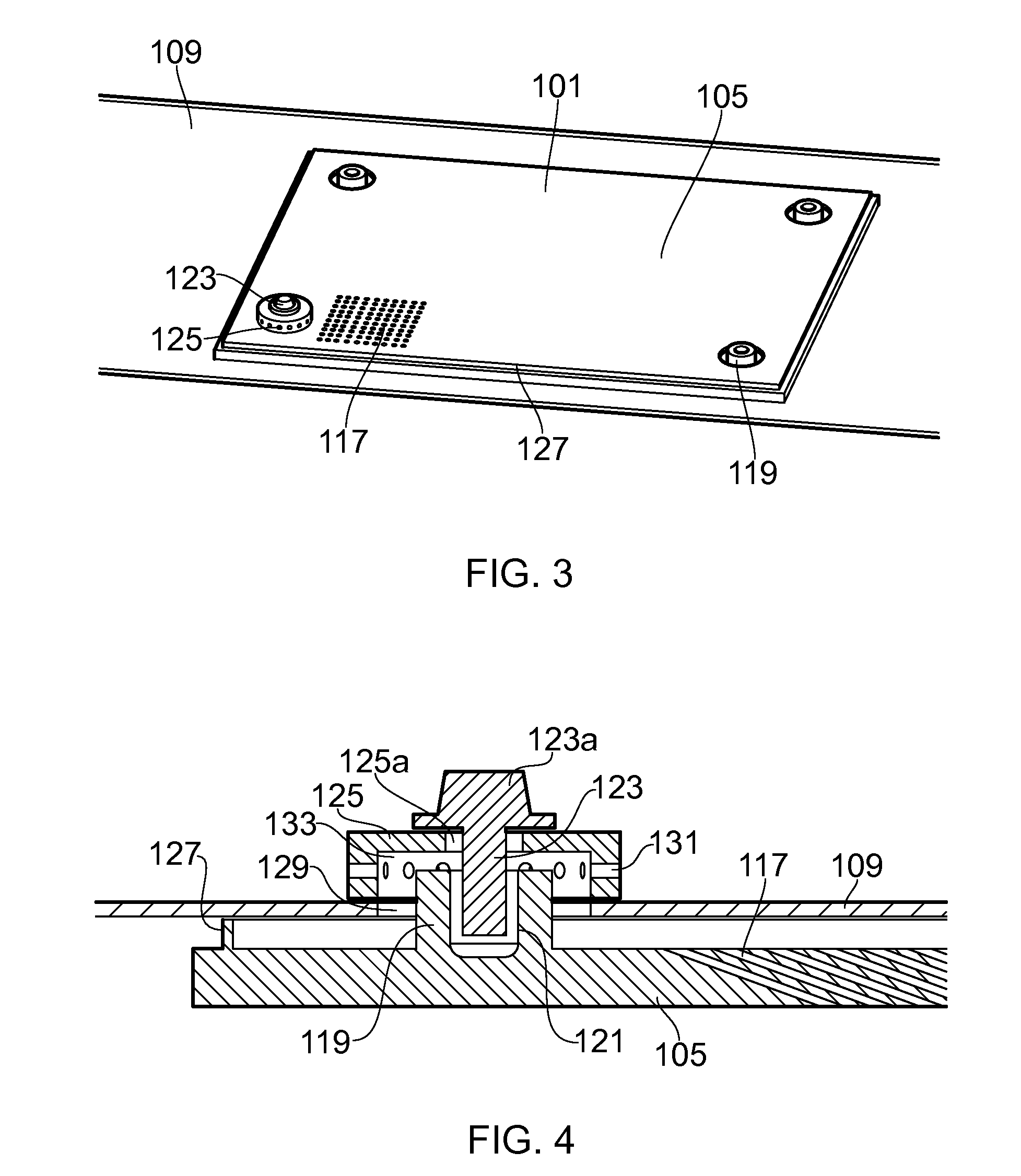
[0028]FIG. 3 shows a schematic perspective view of a tile 101 according to the present invention and the corresponding portion of a combustor wall 109 (i.e. cold skin) to which the tile is fixed. For clarity, the combustor wall is made transparent. Further, the tile and portion of combustor wall are as flat objects, although in reality they would curve around the annulus of the wall. The tile has a rectangular tile body 105, and FIG. 4 shows a schematic cross-section through one of the fixing arrangements, which are provided at the corner regions of the body. An array of cooling air effusion holes 117 traverses the tile body, but in FIGS. 3 and 4 only a small number of these holes are shown.

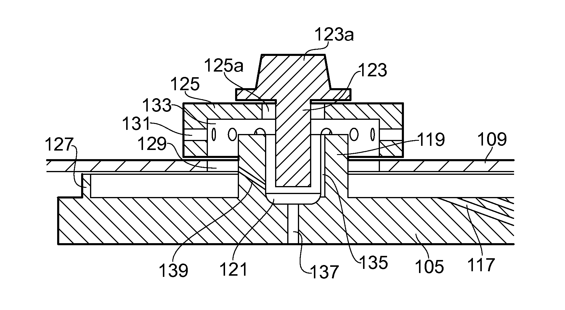
[0029]Each fixing arrangement comprises a boss 119 protruding from the cold side of the tile body 105 to extend through a hole 129 in the combustor wall 109. The boss has a threaded recess 121 into which is screwed a bolt 123 from the cold side of the combustor wall. A ring-shaped spacer 125 enci...

second embodiment

[0034]The tile 105 of the second embodiment has enhancements to improve the cooling of the tile in the vicinity of the boss 119. More specifically, one or more channels 135 run along the side of the recess 121. Cooling air conveyed by the radially extending passages 131 in the spacer 125 is thus carried, via the central cavity 133 of the spacer, to the channel or channels 135 and thence to the foot of the recess. From here, an effusion hole 137 extends across the tile body bringing cooling air to a position directly underneath the boss 119. In an alternative version of the tile, instead of having a channel or channels 135 running along the side of the recess 121, the tile may have one or more channels 139 extending between the recess and the radially outer surface of the boss, e.g. to exit in the hole 129 of the combustor wall 109 (as shown in FIG. 5) or in the central cavity of the spacer.

[0035]The channel or channels 135 running along the side of the recess 121 could be formed dur...


PUM


Abstract

A tile is provided for lining the hot side of a wall of a combustor. The tile has a tile body with one or more bosses protruding from the cold side thereof. The or each boss extends, in use, through the wall of the combustor and has a threaded recess formed therein for threadingly connecting with a bolt which is inserted into the recess from the cold side of the combustor wall. The bolt fastens the tile to the combustor wall.

Description

CROSS REFERENCE TO RELATED APPLICATION[0001]This application is entitled to the benefit of British Patent Application No. GB 0913580.7, filed on Aug. 5, 2010.FIELD OF THE INVENTION[0002]The present invention relates to a tile for lining the hot side of a wall of a combustor.BACKGROUND OF THE INVENTION[0003]The temperature of the gases released by the combustion process in a gas turbine engine may peak above 2100° C. and average 1500° C. This is much higher than the melting point of combustion chamber materials. Thus many gas turbine engine combustors employ ceramic or ceramic-coated tiles to line the combustor wall.[0004]The individual tiles are attached to the combustor wall (e.g. the annular “cold skin” which forms the sides of the combustor) and cooling air passes through holes in the wall to impinge on the cold side of the tiles. The air then moves through a series of pedestals projecting from the cold side of the tiles to improve the convective heat transfer coefficient.[0005]F...

Claims


Application Information

Patent Timeline
IPC IPC(8): F02C7/18F23R3/60B32B3/06
CPCF23R3/002F23R3/007Y10T428/24479F23R2900/03042F23R3/60F23R2900/03041
Inventor CARLISLE, MICHAEL LAWRENCE
Owner ROLLS ROYCE PLC
Why Eureka
Try Eureka