Operational pedal support structure of automotive vehicle

a technology of automotive vehicles and pedal supports, which is applied in the direction of mechanical control devices, instruments, tractors, etc., can solve the problems of deteriorating reliability of the pedal support, rearward movement of the operational pedal, and insufficient compactness of the pedal support structure, so as to achieve high reliability

Inactive Publication Date: 2011-02-10
MAZDA MOTOR CORP
View PDF3 Cites 18 Cited by
  • Summary
  • Abstract
  • Description
  • Claims
  • Application Information

AI Technical Summary

Benefits of technology

[0012]An object of the present invention is to provide an operational pedal support structure of an automotive vehicle equipped with a means for compulsively moving down the pedal at the vehicle frontal collision, which can be made properly compact and simple having a high reliability.

Problems solved by technology

Accordingly, a masterback and the dash panel are pushed rearward, resulting in the rearward move of the operational pedal.
According to the above-described conventional structure, however, since the fixed pedal support member 100 needs a support portion to support the axis 104 because the axis 104 of the rotational lever 105 is positioned in back of the pedal axis 102, there was a problem in that the pedal support structure would not be made properly compact.
Thus, there was a problem in that the reliability of the pedal support would deteriorate.
According to the above-described conventional structure, however, since the fixed pedal support member 201 needs a support portion to support the axis 204 because the axis 204 of the rotational lever 205 is positioned in back of the pedal axis 203, there was a problem in that the pedal support structure would not be made properly compact as well.
According to the above-described conventional structure, however, since the mechanism to compulsively move the pedal body 311 obliquely forward and downward by pulling out the swing pedal support member 305 at the vehicle frontal collision exists in back of the pedal axis 310, there was a problem in that the pedal support structure would not be made properly compact.
Herein, this conventional structure had a problem in that since the mechanism to compulsively move the pedal body 402 exists in back of the pedal axis 403, the pedal support structure would not be made properly compact.
Further, since at the vehicle collision the position of the pedal axis 403 may be constant and the pedal may not drop despite the forward move of the pedal pad 410, there was another problem in that any lower space would not be utilized effectively.
Moreover, since any proper movement may not be obtained in case the links 408, 409 do not move smoothly due to the vehicle frontal collision, there was further another problem in that the reliability would deteriorate, the number of parts would increase, and the structure would become improperly complex.

Method used


Image

  • Operational pedal support structure of automotive vehicle
  • Operational pedal support structure of automotive vehicle
  • Operational pedal support structure of automotive vehicle

Examples


embodiment 1

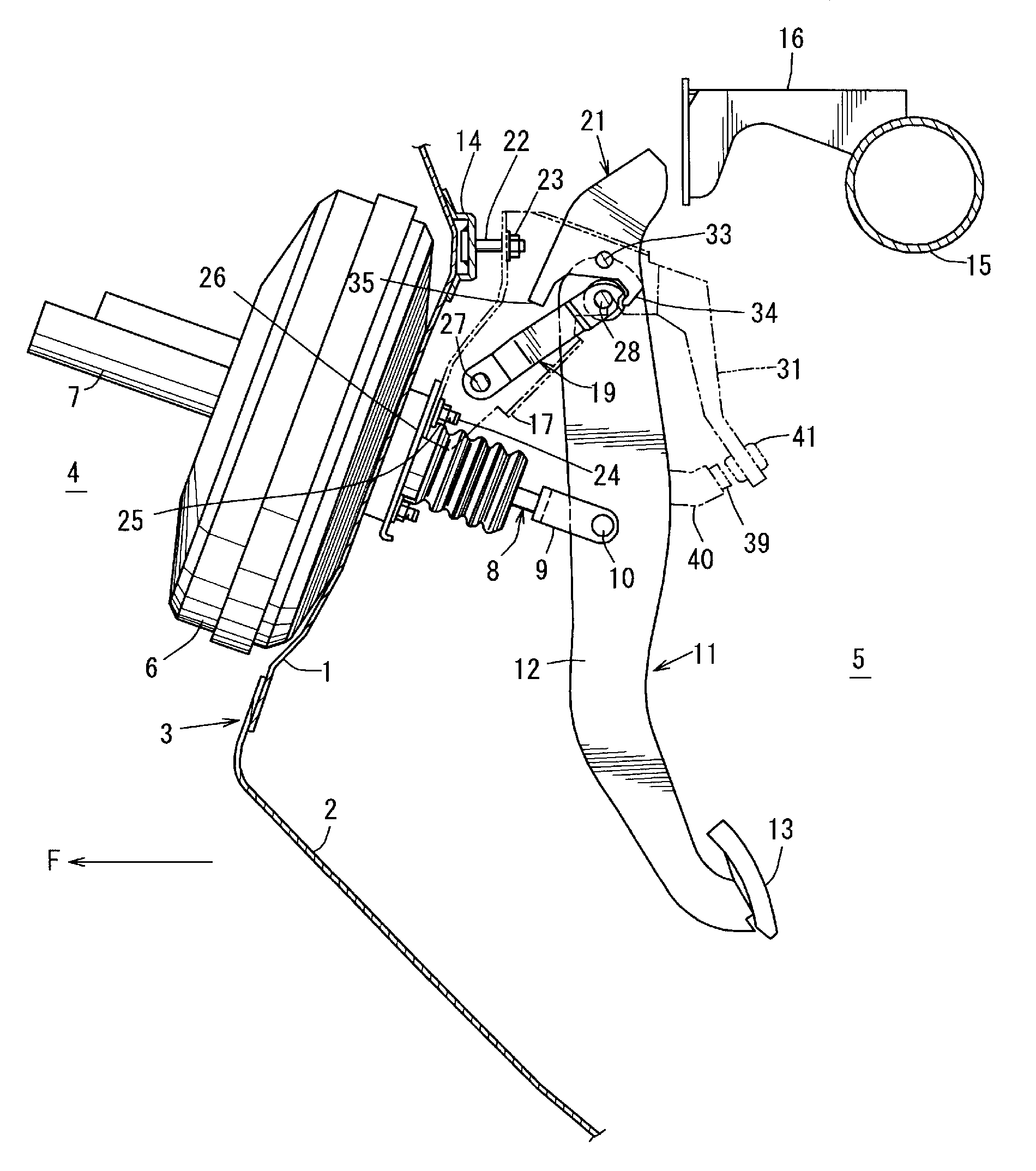
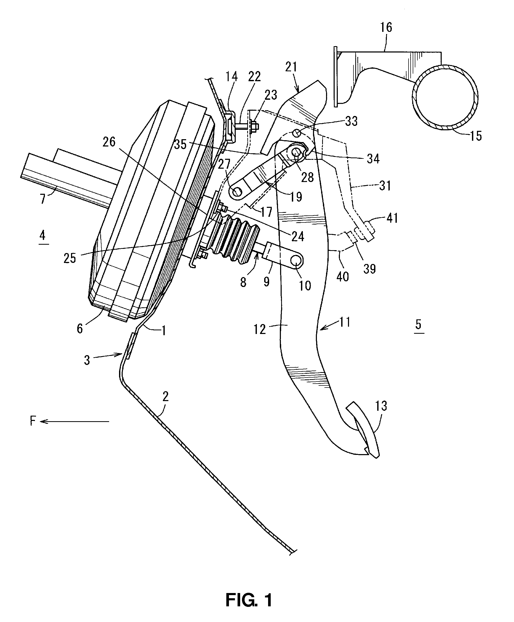
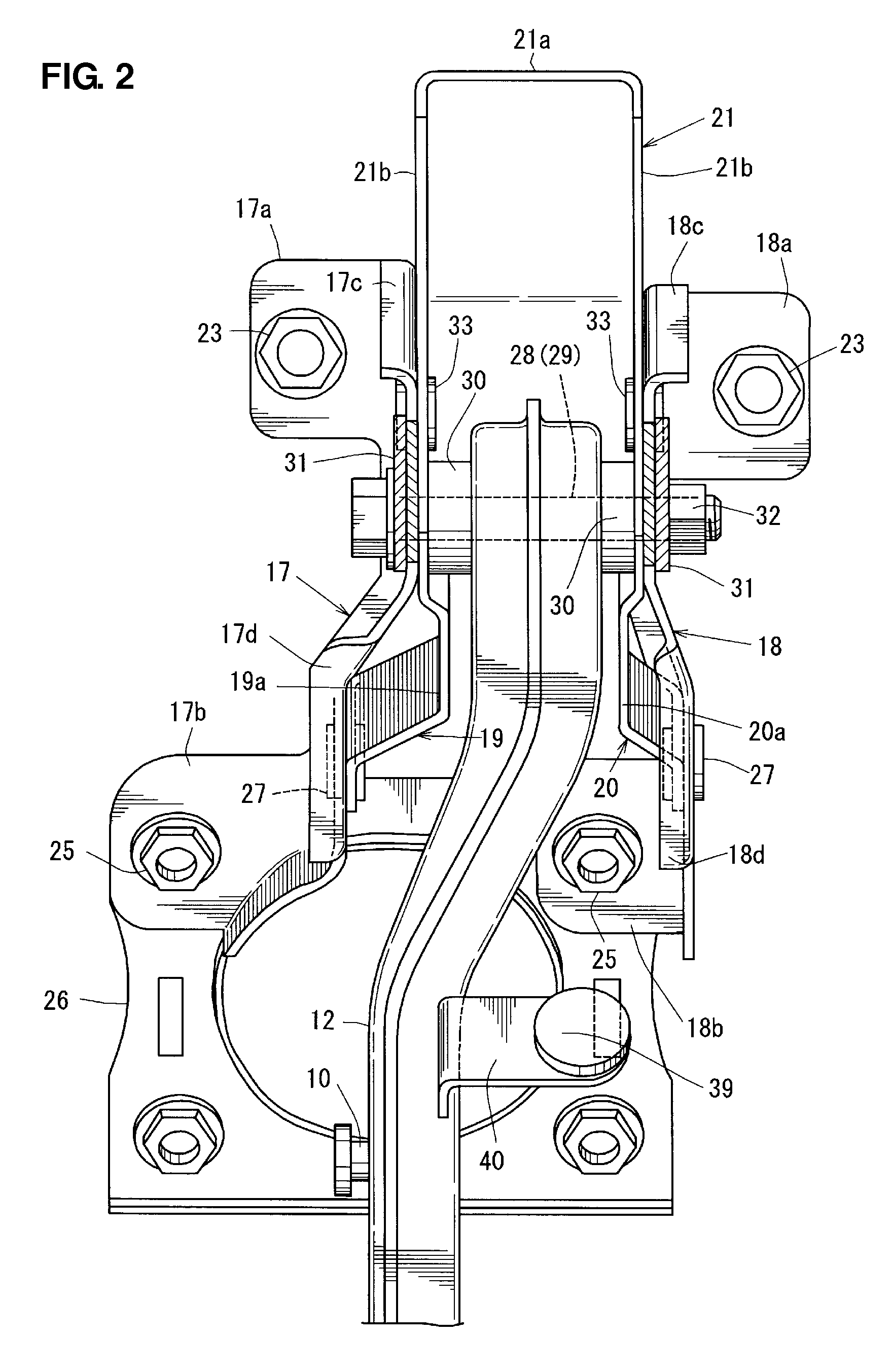
[0040]FIG. 1 is a side view showing an operational pedal support structure of an automotive vehicle according to a first embodiment, FIG. 2 is a back view of the operational pedal support structure of FIG. 1, and FIG. 3 is a plan view of a major part of FIG. 1. In FIG. 1, a dash panel 3 is formed by a dash upper panel 1 (an upper dash-panel) and a dash lower panel 2 (a lower dash-panel) which are joined, which partitions an engine room 4 (a two-kind motor room of a hybrid vehicle) from a vehicle compartment 5 in a vehicle longitudinal direction. Herein, the dash panel 3 is a panel member which constitutes a front portion of the vehicle compartment 5. A masterback 6 and a master cylinder 7 of a brake device are arranged at the dash upper panel 1 on the side of the engine room 4.

[0041]A push rod 8 of the brake device extends toward the vehicle compartment 5, and its rear end is connected to a middle portion of a pedal body 12 of a brake pedal 11 as an operational pedal via a fork 9 an...

embodiment 2

[0081]FIGS. 11 through 15 show an operational pedal support structure of an automotive vehicle according to another embodiment. The operational pedal support structure of an automotive vehicle of the present embodiment is arranged in back of the dash panel 3 (see the previous figures) which constitutes the front portion of the vehicle compartment 5.

[0082]Further, the operational pedal support structure of the present embodiment, as shown in FIG. 11, comprises a mount bracket 50 as the fixed pedal support member which is provided on the side of the dash panel 3, a swing arm 51 as the swing arm pedal support member which is supported relative to the mount bracket 50 so as to swing in the vertical direction around a pin 27 provided at its front portion and extends obliquely upward and rearward, the pedal body 12 which is supported via the pedal axis 28 as the first pivotal axis, which is arranged at a rear portion of the swing arm 51 and extends in the vehicle width direction, so as to...


PUM


Abstract

An operational pedal support structure of an automotive vehicle comprises a fixed pedal support member on the side of a dash panel, a swing pedal support member, a pedal body supported at the swing pedal support member via a first pivotal axis, a downward-move restricting means to allow a downward move of the first pivotal axis only in case the rotational lever rotates, and a pressing portion provided at the rotational lever so as to press down the swing pedal support member. The pressing portion is positioned in front of the second pivotal axis. Accordingly, the operational pedal support structure of an automotive vehicle equipped with a means for compulsively moving down the pedal at the vehicle frontal collision, which can be made compact and simple with a high reliability, can be provided.

Description

BACKGROUND OF THE INVENTION[0001]The present invention relates to an operational pedal support structure of an automotive vehicle which can restrain a rearward move of a pedal pressing face (so-called pedal pad) of an operational pedal provided in back of a dash panel at a vehicle frontal collision.[0002]In general, when the automotive vehicle has a frontal collision, a power train, such as an engine, (or an engine and a motor of a hybrid vehicle) provided in front of the dash panel moves rearward. Accordingly, a masterback and the dash panel are pushed rearward, resulting in the rearward move of the operational pedal. Some inventions regarding the operational pedal support structure of an automotive vehicle which can provide a so-called rearward move restraint mechanism to restrain the rearward move of the operational pedal for ensuring the safety of a passenger have been made (see the following patent documents).[0003]A conventional structure disclosed in PCT Publication No. WO03 / ...

Claims


Application Information

Patent Timeline
Patent Type & Authority Applications(United States)
IPC IPC(8): G05G1/30
CPCB60R21/09Y10T74/20528G05G1/327B60T7/065
Inventor TOKUMO, MASAYUKIYAMAZAKI, YOH
Owner MAZDA MOTOR CORP
Why Eureka
Try Eureka