Ribbed Water Spike

a technology of ribbed water and water spike, which is applied in the direction of liquid handling, instruments, volume metering, etc., can solve the problem of hardening the dispensing device to be removed

Active Publication Date: 2011-02-10
INT PACKAGING INNOVATIONS
View PDF23 Cites 14 Cited by
  • Summary
  • Abstract
  • Description
  • Claims
  • Application Information

AI Technical Summary

Problems solved by technology

Due to these and other problems in the art, disclosed herein is a ribbed spiked water dispensing device comprised of a shaft with at least one rib on its exterior surface and a spik

Method used


Image

  • Ribbed Water Spike
  • Ribbed Water Spike
  • Ribbed Water Spike

Examples


Embodiment Construction

)

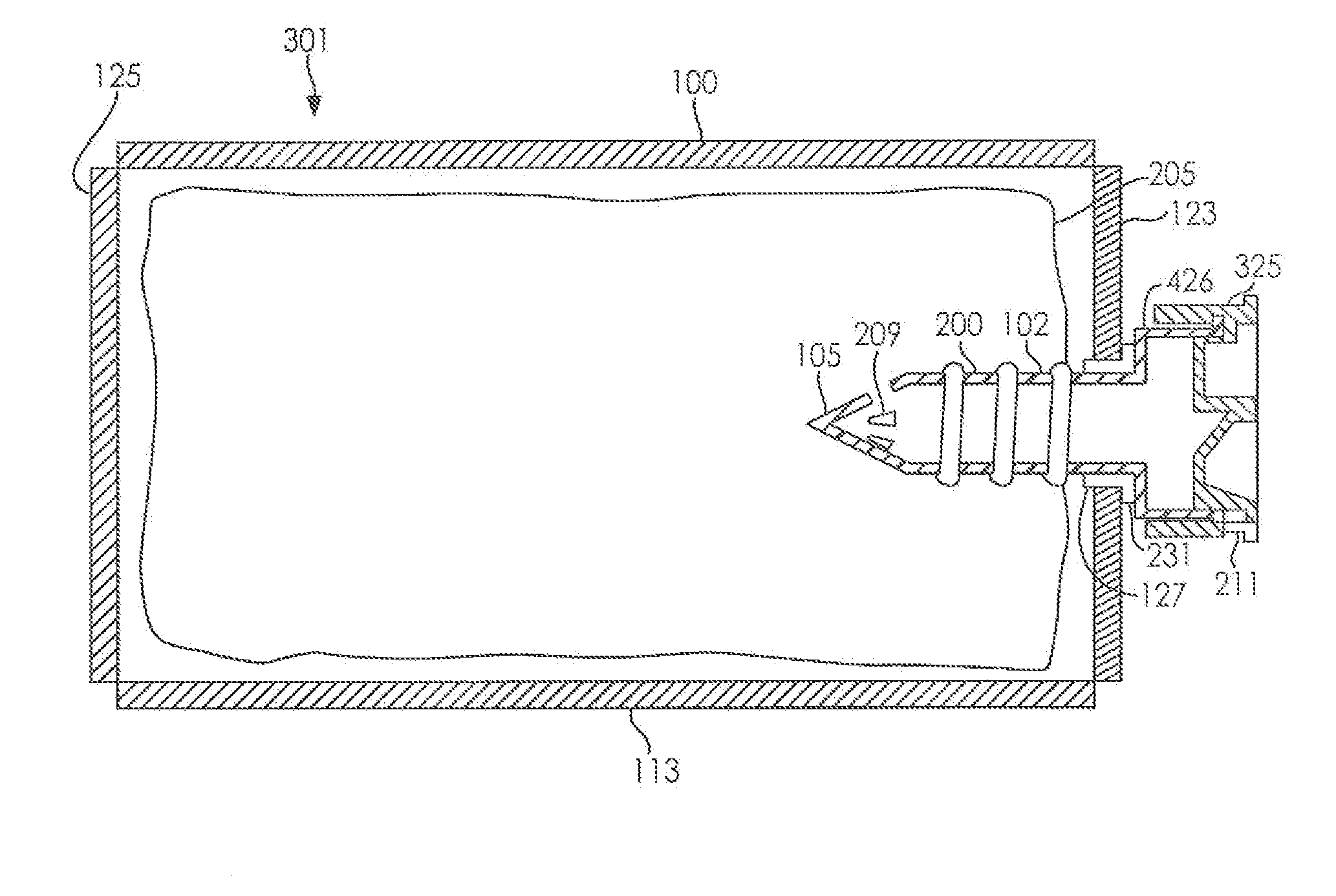
[0066]With reference to FIGS. 1-17, a ribbed spiked water dispensing device will be described according to several embodiments of the present invention.

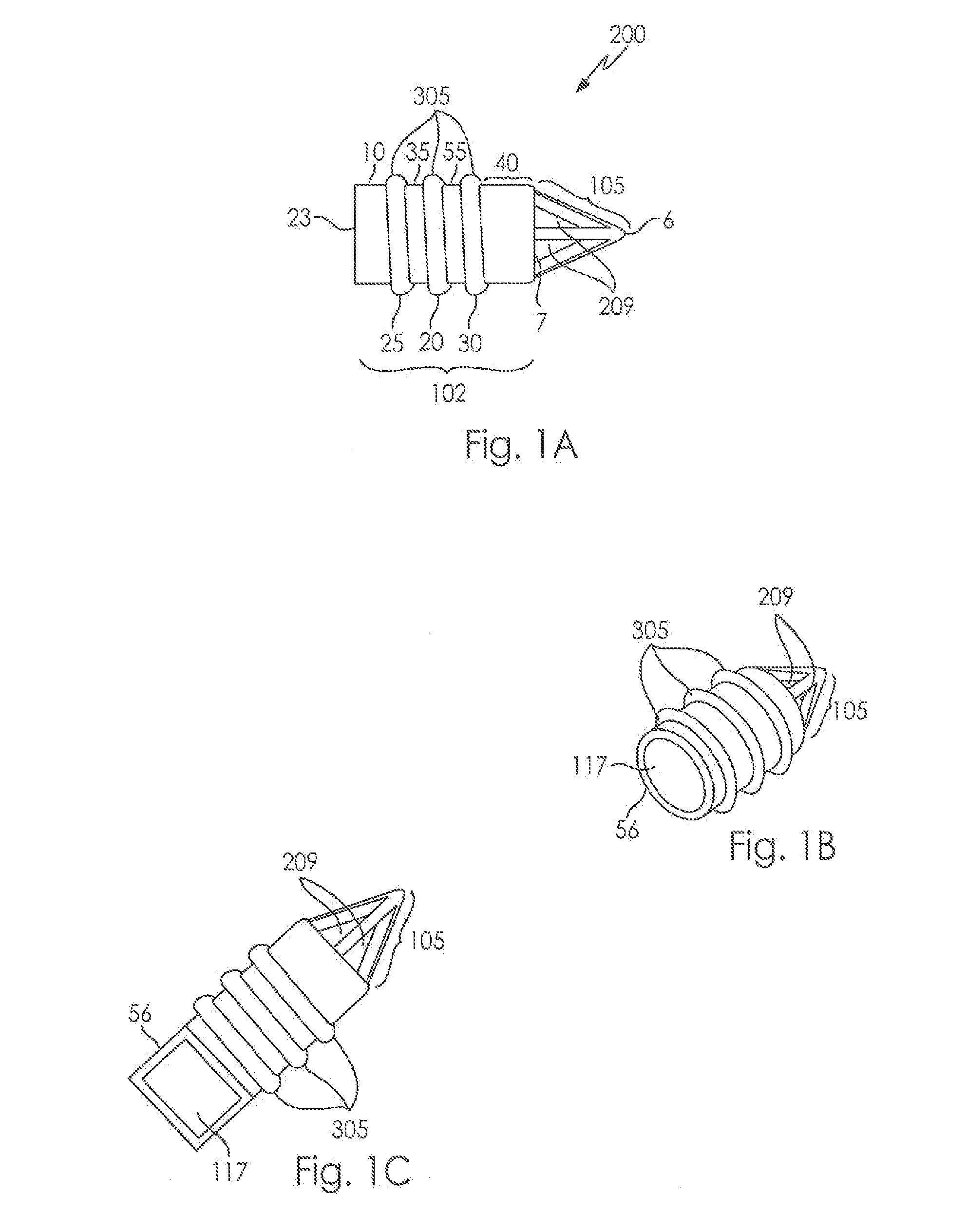
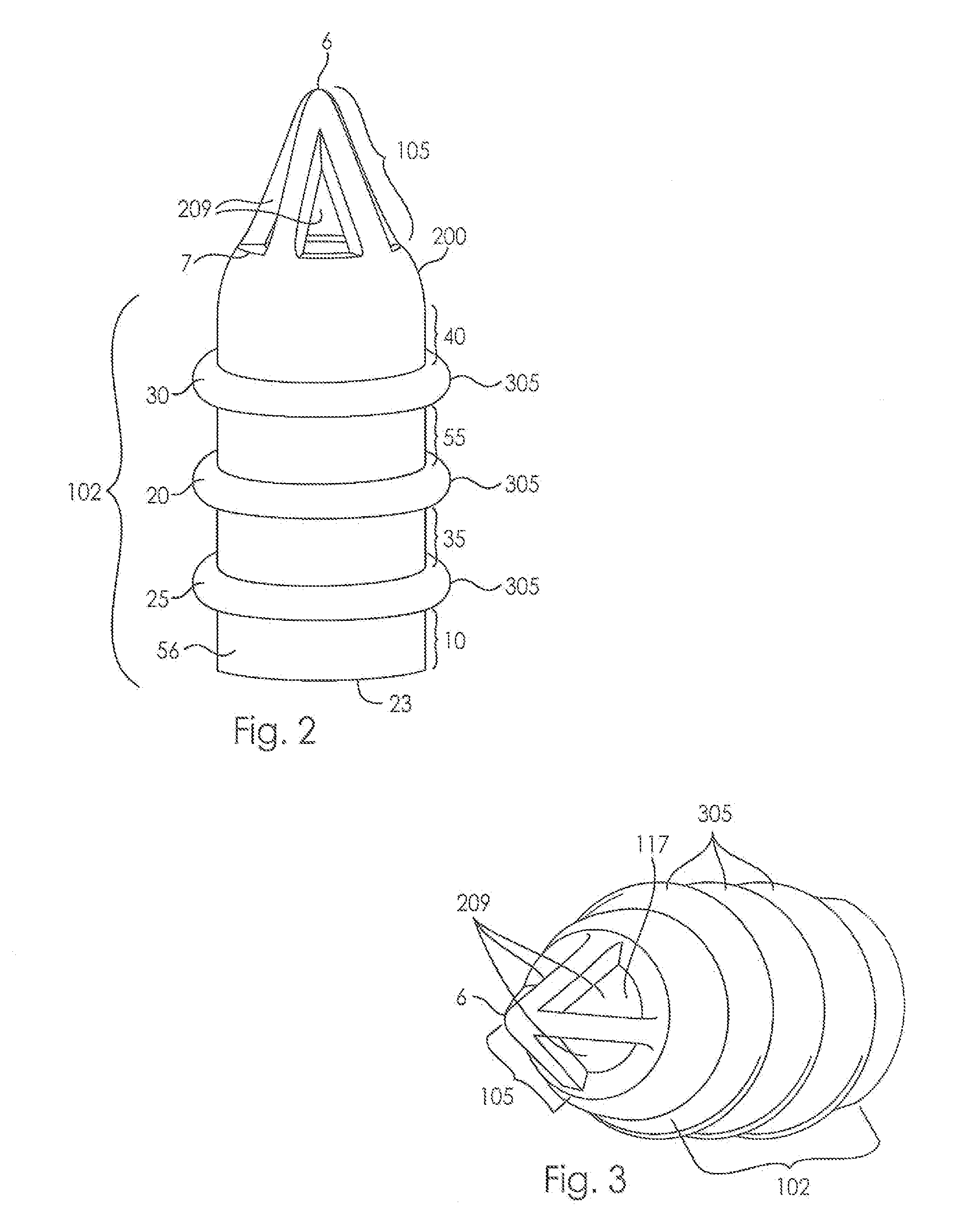
[0067]Turning now to FIG. 1, a ribbed spiked water dispensing device (200), in accordance with one embodiment of the invention, is shown. Generally made of plastic, the ribbed spiked fluid dispensing device (200) pictured in FIG. 1 is generally comprised of four main elements: a shaft (102), a spiked tip (105), openings in the spiked tip (209), and one or more ribs (305).

[0068]The shaft (102) of the ribbed spiked fluid dispensing device (200) of FIGS. 1A, 1B and 1C has an internal volume (117) and an exterior shell (56). It is contemplated that the shaft (102) of the fluid dispensing device (200) can take on a number of different shapes. As seen in FIGS. 1A and 1B, in one embodiment the shaft (102) is cylindrical in shape; specifically the shaft (102) is a circular cylinder. Generally, any cylindrical shape with an internal volume (...


PUM


Abstract

A ribbed spike for use with dispensing a fluid, such a water, from a bag. The spike includes a plurality of ribs or undulations on its outer surface which can improve connection strength to a bag of fluid. Systems and methods for using such a spike in the dispensing of fluid in a variety of situations are also provided.

Description

CROSS REFERENCE TO RELATED APPLICATION(S)[0001]This Application claims the benefit of U.S. Provisional Patent Application Ser. No: 61 / 167,044, filed Apr. 6, 2009, the entire disclosure of which is herein incorporated by reference.BACKGROUND OF THE INVENTION[0002]1. Field of the Invention[0003]This disclosure relates to the field of systems for dispensing of fluids. In particular, to the field of fluid dispensing systems wherein a bagged fluid, such as water, is dispensed via a ribbed water spike.[0004]2. Description of Related Art[0005]Liquid storage vessels such as jugs or pitchers are essentially ubiquitous in society and have been around in a general form for centuries. A liquid storage vessel generally serves two purposes. It serves to contain a liquid so that the liquid does not spill, evaporate, or be soaked up by other objects from which it cannot easily be removed, and it serves as a way to dispense the liquid to users to drink, wash with, or otherwise utilize.[0006]As techn...

Claims


Application Information

Patent Timeline
IPC IPC(8): B67D1/00G01F11/00
CPCB65D25/48B67B7/24B65D77/068B65D75/5877
Inventor MACLER, JEFFREY E.
Owner INT PACKAGING INNOVATIONS
Why Eureka
Try Eureka