Tip end bracket

a technology of mounting brackets and end brackets, which is applied in the direction of transportation items, machines/engines, manufacturing tools, etc., can solve the problems of limiting the available space for transportation, increasing the complexity of the blade transportation from the fabrication location to the operation location, etc., and preventing a blade damage. , the effect of easing the change of the transportation devi

Active Publication Date: 2011-02-10
SIEMENS GAMESA RENEWABLE ENERGY AS
View PDF30 Cites 52 Cited by
  • Summary
  • Abstract
  • Description
  • Claims
  • Application Information

AI Technical Summary

Benefits of technology

[0014]By using the mounting bracket device, an adjustable and flexible transportation device for a blade of a wind turbine may be provided, so that the mounting bracket device is adjustable and flexible to different ways of transportation Thus, the blade may be transported in a safer way, so that damages of the blade during the transportation may be avoided. The connecting system of the mounting bracket device provides a connection for truck, rail and sea transport devices without any changes in the design of the mounting bracket device itself. Furthermore, the adjustment system of the mounting bracket device provides a way of adjusting the blade in different angle positions around at least two rotary axes, so that, depending on the way of the transportation, desired angle positions may be adjusted. Thus, a flexible adjustment around two rotary axes may be provided, so that an improved alignment to a variety of different restrictions of different transportation devices may be provided. Furthermore, by using the connecting systems adapted for being removably fixed to the transportation device, it is possible to clamp the blade with the clamping device at the location of fabrication and the mounting bracket device is fixable to different types of transportation devices without the need of taking the blade out of the clamping device.
[0027]According to a further exemplary embodiment, the clamping device comprises a transport opening. The transport opening is adapted for receiving a strap lashing for fixing the blade. Thus, the blade may be wrapped by the strap lashing or a belt in order to provide a further fixation means of the blade to the mounting bracket device. By providing a transport opening at the clamping device, the strap lashing may be fixed to the mounting bracket device, so that no further connections at the transportation device are necessary. Thus, a change of the transportation device is eased.

Problems solved by technology

When increasing the size of the blades of the wind turbines, the transportation of the blades from the fabrication location to the location of operation is getting more and more complex.
Thus, by transporting the blades by these conventional transportation means, the available space for transportation is restricted by the environment, i.e. when transporting a blade by train or by truck the blades have to be fit to conventional tunnels or allowable heights in order to fit under it, for example.

Method used


Image

  • Tip end bracket
  • Tip end bracket
  • Tip end bracket

Examples


Embodiment Construction

[0044]The illustration in the drawing is schematically. It is noted that in different figures, similar or identical elements are provided with the same reference signs or with reference signs, which are different from the corresponding reference signs only within the first digit. The view in the figures is schematic and not fully scaled.

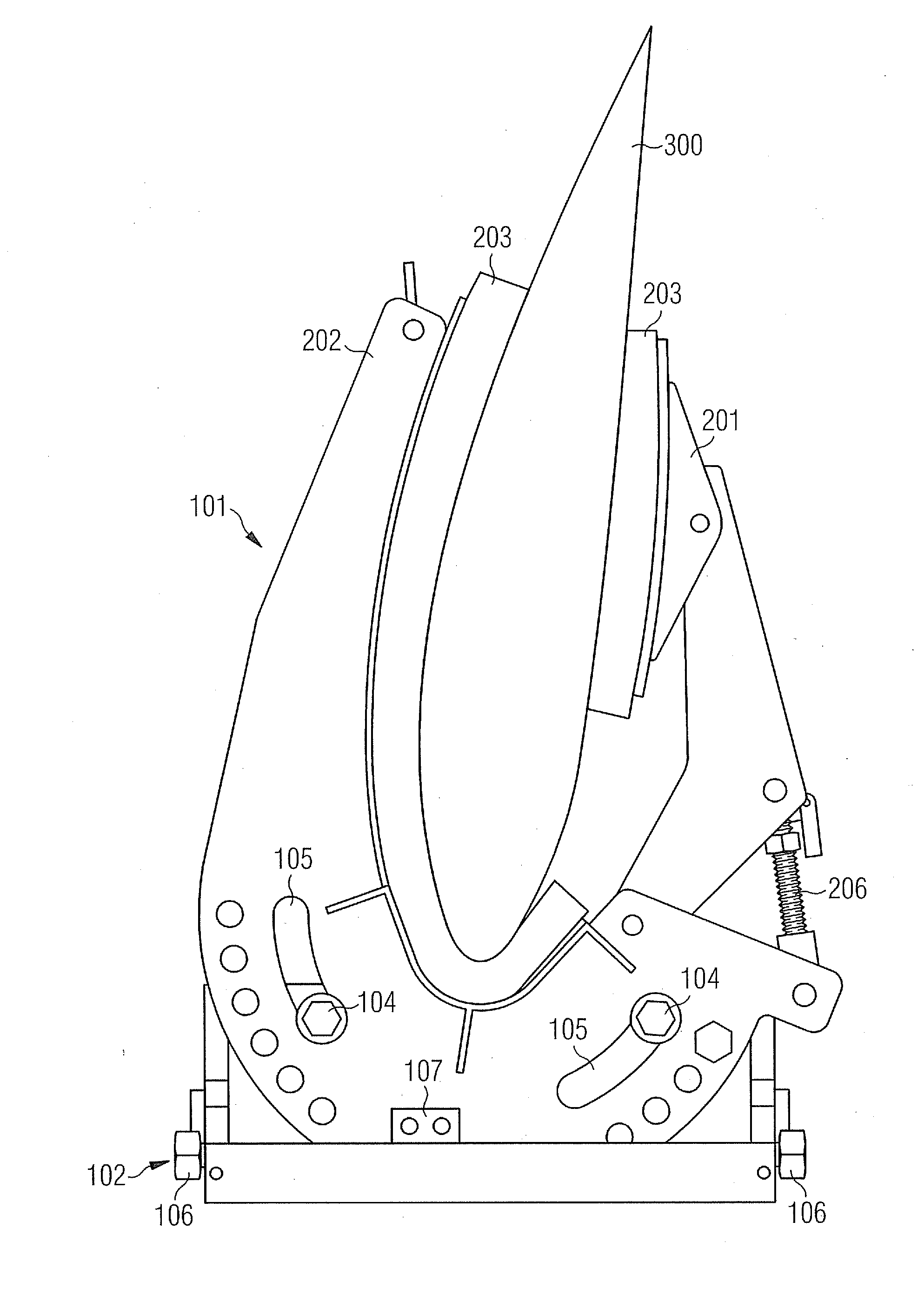
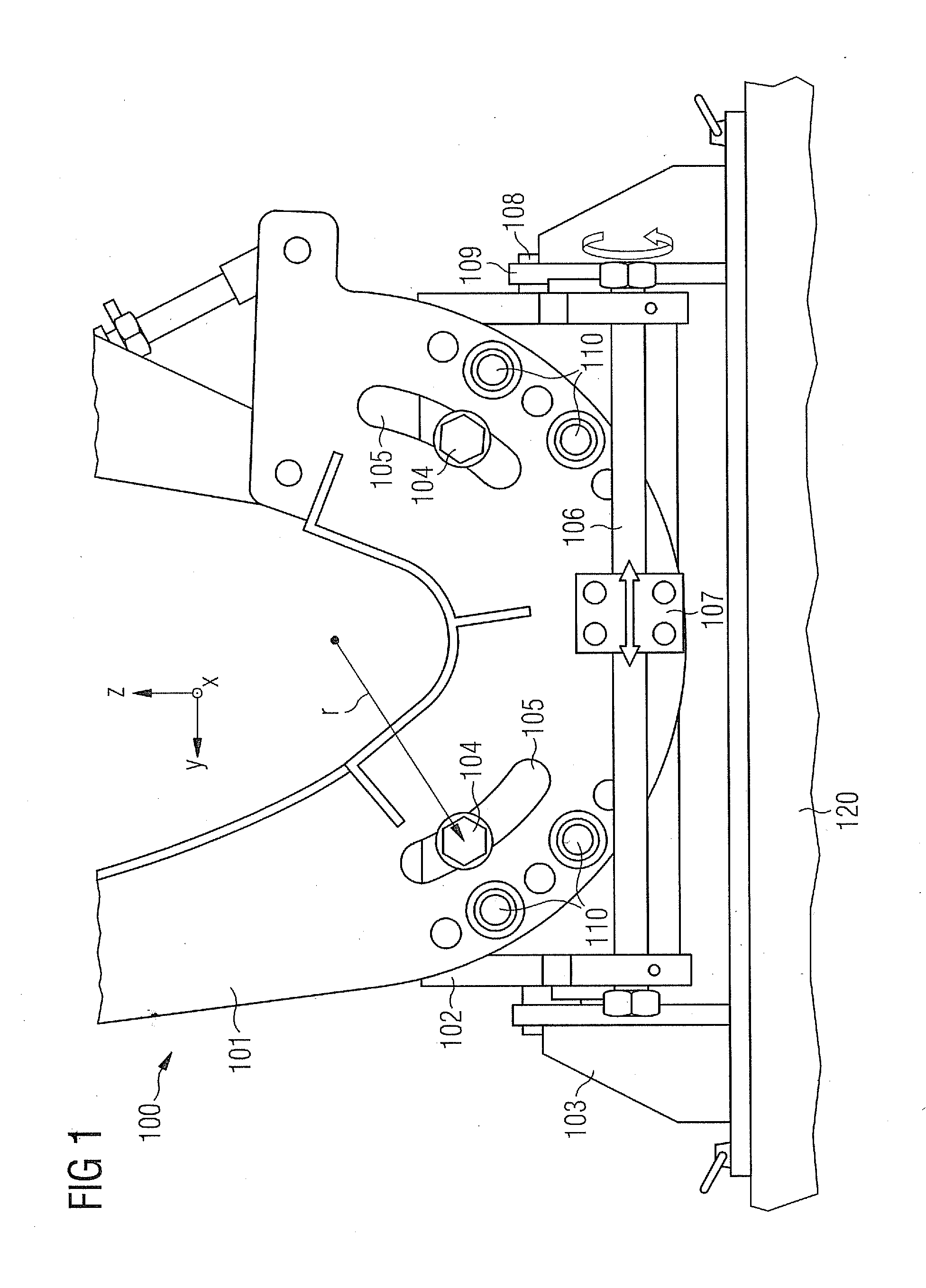
[0045]FIG. 1 illustrates a schematic view of one exemplary embodiment of the present invention. A mounting bracket device 100 for mounting a blade 300 of a wind turbine to a transportation device 120 is shown. The mounting bracket device 100 comprises a clamping device 101 for holding the blade 300 rigidly, an adjustment system 102 and a connecting system 103 adapted for being removably fixed to the transportation device 120. The connecting system 103 connects the clamping device 101 and the adjustment system 102 to the transportation 120. The adjustment system 102 is adapted to align the clamping device 101 with respect to the transportation device ...


PUM

PropertyMeasurementUnit
sizeaaaaaaaaaa
energyaaaaaaaaaa
diametersaaaaaaaaaa

Abstract

A mounting bracket device and method for mounting a blade of a wind turbine to a transportation device are disclosed. The mounting bracket device includes a clamping device for holding the blade, an adjustment system, and a connecting system adapted for being removably connected to the transportation device. The connecting system removably connects the clamping device and the adjustment system to the transportation device. The adjustment system is adapted to align the clamping device with respect to the transportation device around the first rotary axis and around a second rotary axis.

Description

FIELD OF INVENTION[0001]The present invention relates to a mounting bracket device for mounting a blade of a wind turbine to a transportation device. Moreover, the present invention relates to a method of mounting a blade of a wind turbine to a transportation device.ART BACKGROUND[0002]In modern times, energy is produced more and more by regenerative energy sources, such as wind turbines. In order to increase the efficiency of wind turbines, blades of the wind turbines are getting larger and larger. When increasing the size of the blades of the wind turbines, the transportation of the blades from the fabrication location to the location of operation is getting more and more complex.[0003]Transportation of a wind turbine blade is done by trucks, trains or ships. Thus, by transporting the blades by these conventional transportation means, the available space for transportation is restricted by the environment, i.e. when transporting a blade by train or by truck the blades have to be f...

Claims


Application Information

Patent Timeline
Patent Type & Authority Applications(United States)
IPC IPC(8): B60R11/00B23P11/00
CPCB60P3/40F03D1/005Y10T29/49959Y02E10/722F03D11/00F03D80/00F03D13/40F03D80/70Y02E10/72
Inventor KROGH, MIKKEL VERNERMADSEN, JONAS
Owner SIEMENS GAMESA RENEWABLE ENERGY AS
Why Eureka
Try Eureka