Supercharge Your Innovation With Domain-Expert AI Agents!

Landing gear with composite leaf spring

a technology of landing gear and leaf spring, which is applied in the direction of landing gear, transportation and packaging, undercarriage, etc., can solve the problems of a large number of problems, create drag, and the landing gear is not suitable for use on a large aircraft, so as to reduce the build up of tensile forces

Active Publication Date: 2011-02-10
AIRBUS OPERATIONS LTD
View PDF18 Cites 19 Cited by
  • Summary
  • Abstract
  • Description
  • Claims
  • Application Information

AI Technical Summary

Benefits of technology

[0006]The arm can be made relatively stiff in comparison with the leaf spring, so that load is transferred directly into the pivot without a large amount of bending of the leg. The leaf spring shock absorber typically has a reduced part count compared with a conventional oleo-pneumatic shock absorber. By forming the leaf spring from a composite material, its weight is significantly reduced in comparison with a conventional metal spring, making it suitable for use on a relatively large aircraft (for instance an aircraft weighing more than 10 tonnes).
[0010]A proximal end of the leaf spring may be directly coupled to the support, or more preferably it is coupled via a swinging link which reduces the build up of tensile forces in the spring.

Problems solved by technology

This arrangement suffers from a number of problems.
Firstly, the landing gear is not retractable so creates drag during cruise of the aircraft.
Secondly, the landing gear is not suitable for use on a large aircraft because it is too heavy.
Thirdly, it has poor lateral stability, as there is very little damping present.
Fourthly, as the composite leg bends upwards the wheel splays outwards, causing undesirable stresses in the wheel assembly.
Although effective, the oleo-pneumatic shock absorber suffers from a number of problems, including: gas leakage; oil leakage; incorrect servicing; seal wear; friction; temperature effects; corrosion; and need for maintenance.

Method used


Image

  • Landing gear with composite leaf spring
  • Landing gear with composite leaf spring
  • Landing gear with composite leaf spring

Examples


Embodiment Construction

)

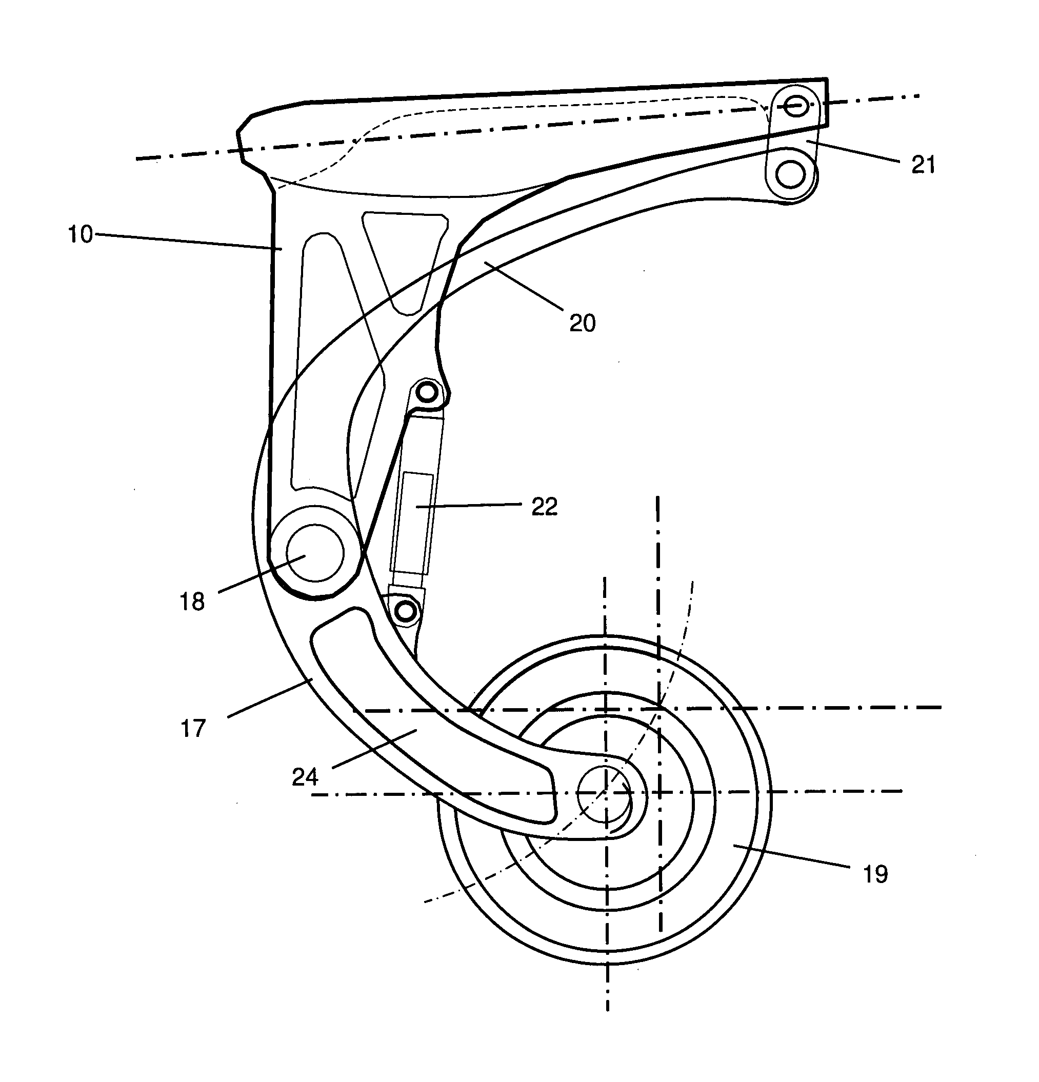
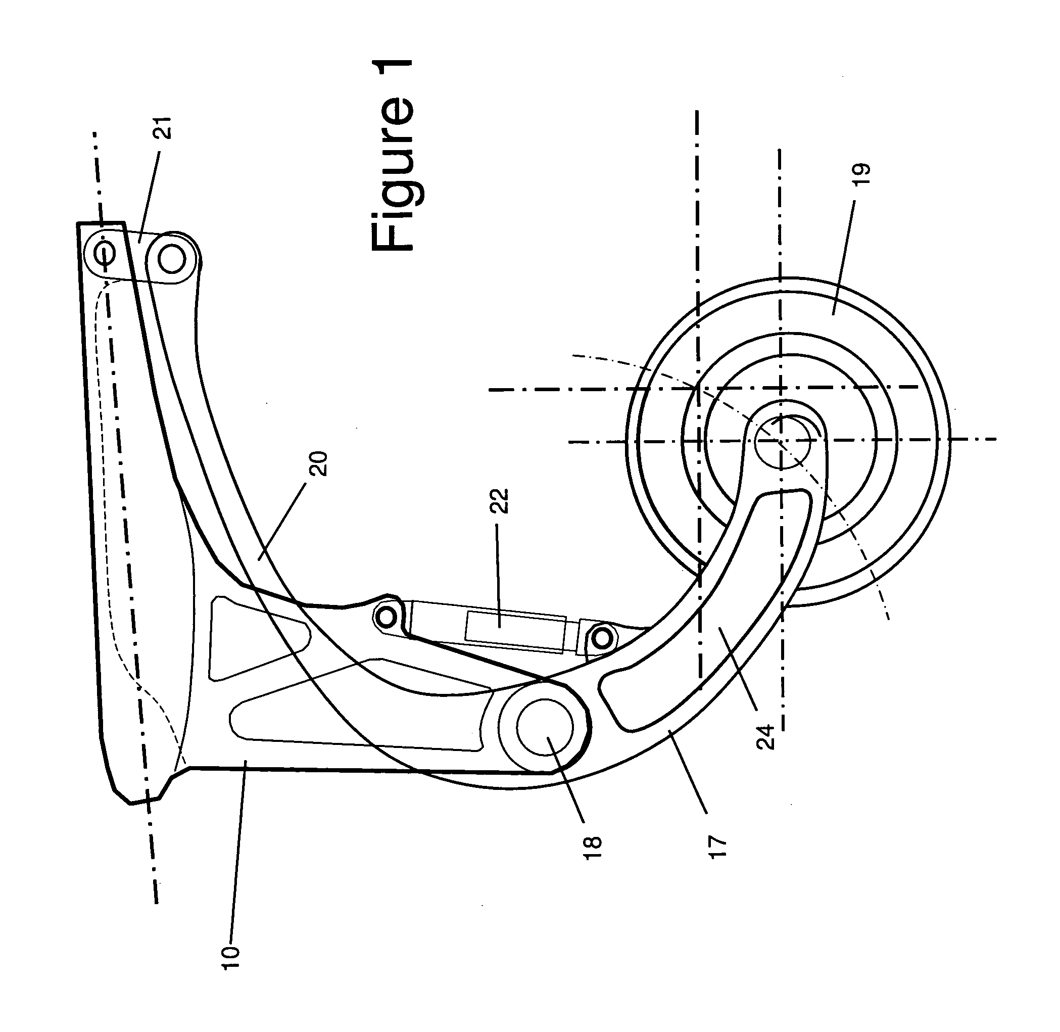
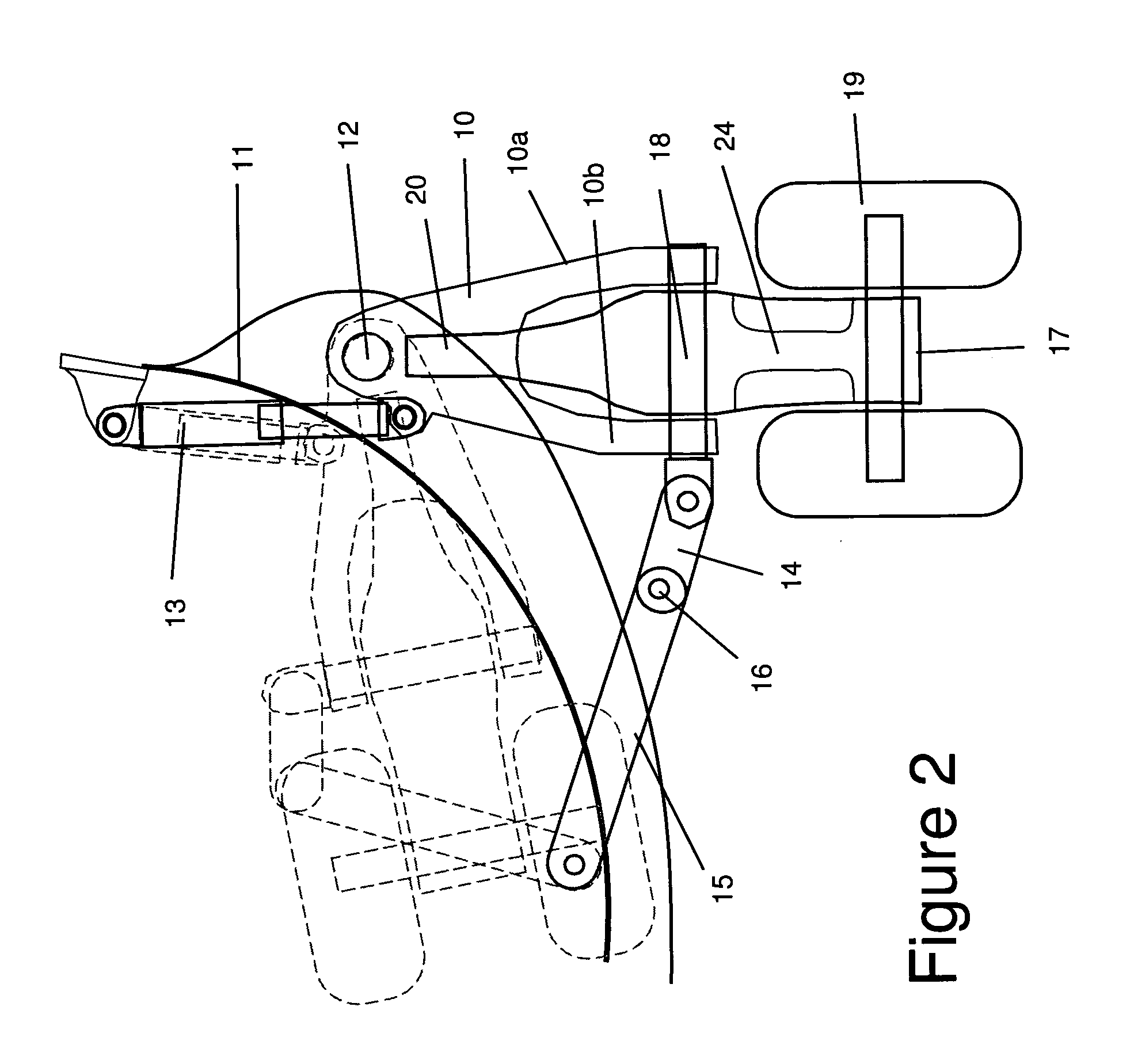
[0022]An aircraft landing gear shown in FIGS. 1-3 comprises a retractable support 10 pivotally attached to the body 11 of an aircraft at a pivot 12. An electric or hydraulic linear retraction actuator 13 can rotate the support 10 about the pivot 12 between a deployed position shown in FIG. 2 in solid line and a retracted position shown in FIG. 2 in dashed line. A pair of links 14, 15 with a central pivot joint 16 can be locked to fix the support 10 in its deployed position. A separate uplock (not shown) may be used to maintain the support in its retracted position, or the links 14, 15 may lock with the gear in the retracted position. The lock can be effected by either locking the joint 16 or an additional set of lock links attaching joint 16 to another point on the support 10 or airframe.

[0023]The support 10 has a pair of clevis arms 10a, 10b which carry a pivot pin 18. A rigid arm 17 is pivotally mounted to the support 10 by the pin 18 and carries a double wheel assembly 19 at its...


PUM


Abstract

An aircraft landing gear comprising: an arm mounted to a pivot and carrying one or more wheel assemblies; and a composite leaf spring which is coupled to the arm and arranged to provide a resilient biasing force which opposes rotation of the arm about the pivot. The arm can be made relatively stiff in comparison with the leaf spring, so that load is transferred directly into the pivot without a large amount of bending of the leg. The leaf spring shock absorber typically has a reduced part count compared with a conventional oleo-pneumatic shock absorber. By forming the leaf spring from a composite material, its weight is significantly reduced in comparison with a conventional metal spring, making it suitable for use on a relatively large aircraft.

Description

FIELD OF THE INVENTION[0001]The present invention relates to a landing gear with a composite leaf spring.BACKGROUND OF THE INVENTION[0002]A non-retractable landing gear with a composite leg carrying a wheel is described in US2006 / 0284009. In a loaded position the composite leg is bent upwardly by the forces associated with landing the aircraft. This arrangement suffers from a number of problems. Firstly, the landing gear is not retractable so creates drag during cruise of the aircraft. Secondly, the landing gear is not suitable for use on a large aircraft because it is too heavy. Thirdly, it has poor lateral stability, as there is very little damping present. Fourthly, as the composite leg bends upwards the wheel splays outwards, causing undesirable stresses in the wheel assembly.[0003]Conventionally, in a retractable landing gear for a larger aircraft, an oleo-pneumatic shock absorber is provided to absorb the majority of the landing loads. Although effective, the oleo-pneumatic sh...

Claims


Application Information

Patent Timeline
IPC IPC(8): B64C25/10B64C25/62
CPCB64C25/12B64C25/62B64C25/18B64C25/14
Inventor THOMPSON, ROBERT IAN
Owner AIRBUS OPERATIONS LTD
Features
  • R&D
  • Intellectual Property
  • Life Sciences
  • Materials
  • Tech Scout
  • Unparalleled Data Quality
  • Higher Quality Content
  • 60% Fewer Hallucinations
Learn More