Discharge Circuit for Smoothing Capacitor of DC Power Supply

a technology of dc power supply and discharge circuit, which is applied in the direction of safety/protection circuit, emergency power supply arrangement, electric generator control, etc., can solve the problem of large current flowing in the discharge circuit for a long time, and achieve the effect of preventing discharge and preventing discharge curren

Active Publication Date: 2011-02-10
HITACHI ASTEMO LTD
View PDF9 Cites 80 Cited by
  • Summary
  • Abstract
  • Description
  • Claims
  • Application Information

AI Technical Summary

Benefits of technology

[0014]According to the 6th aspect of the present invention, in the discharge circuit for a DC power supply smoothing capacitor according to any one of the aspects 3 through 5, it is preferred that the control circuit lengthens the time intervals in correspondence to elapsed time after start of discharge.
[0019]According to the present invention, even if during discharge of the capacitor by the resistor the switch stays ON for some reason, it is still possible reliably to prevent discharge by the resistor, and it is possible to prevent a discharge current from continuing to flow in the resistor.

Problems solved by technology

However with the prior art control device described above if, after the automobile has been stopped, for some reason the contactor turns to ON (closed) after the start of discharging of the capacitor by the discharge circuit, then because the current from the battery flows the discharge circuit, a large current will continue to flow in the discharge circuit for quite a long period of time.

Method used


Image

  • Discharge Circuit for Smoothing Capacitor of DC Power Supply
  • Discharge Circuit for Smoothing Capacitor of DC Power Supply
  • Discharge Circuit for Smoothing Capacitor of DC Power Supply

Examples


Embodiment Construction

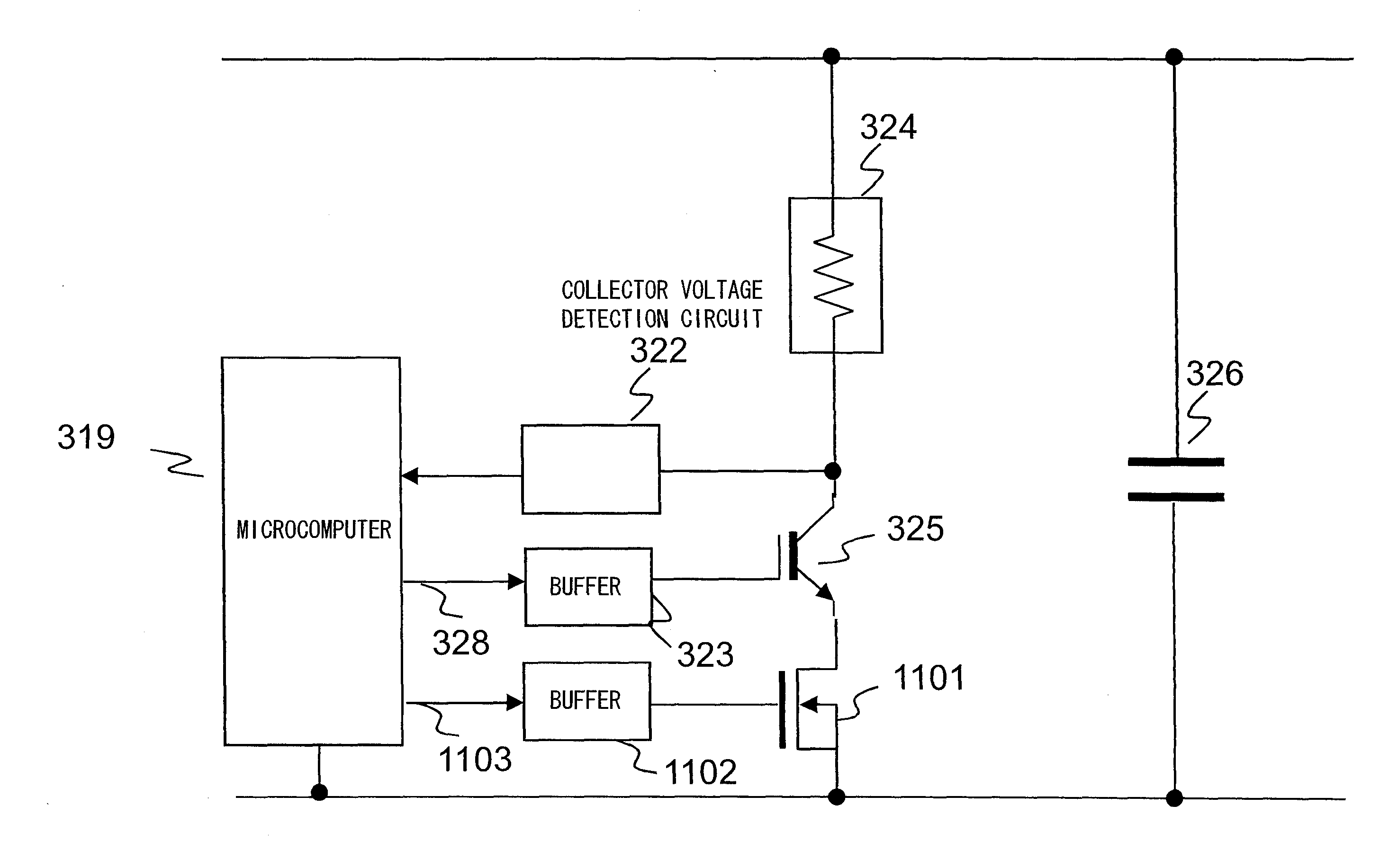
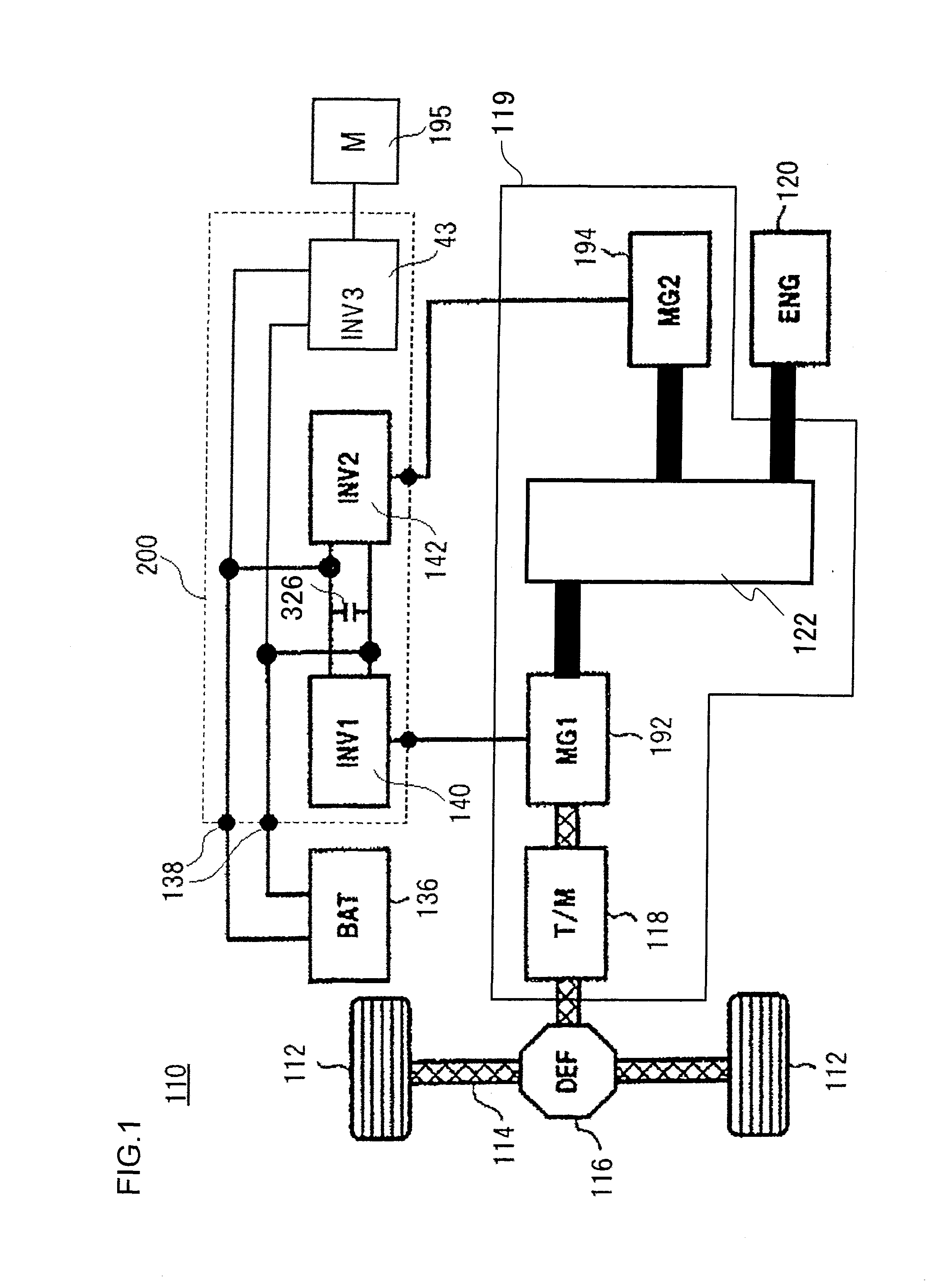
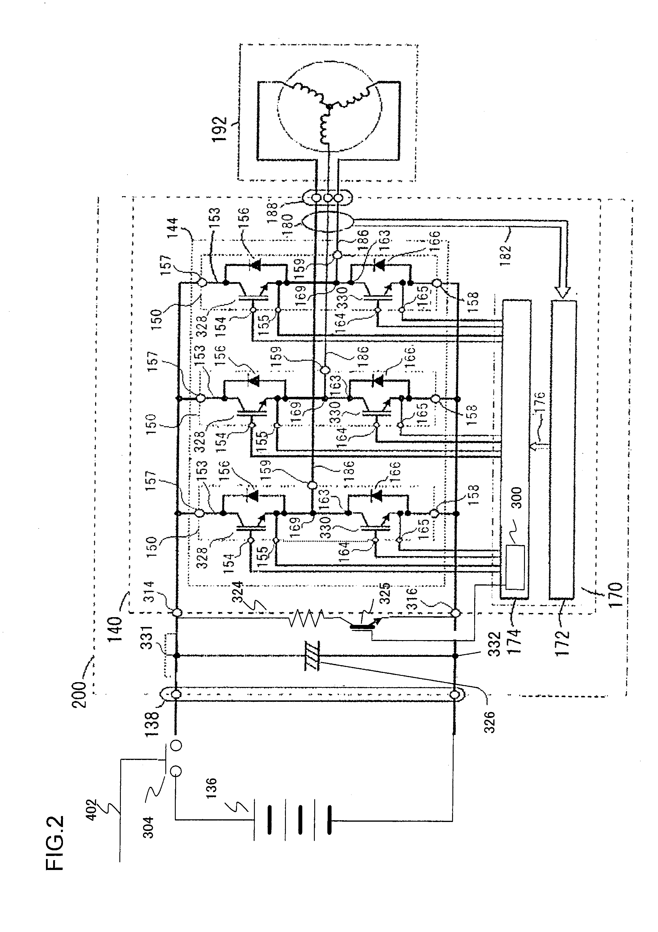
[0035]Various embodiments of the present invention as applied to an inverter for driving a motor of a hybrid automobile will now be explained. It should be understood that the discharge circuit for a smoothing capacitor of a DC power supply of the present invention is not limited to this application to an inverter for driving the motor of a hybrid automobile; it can also of course be applied to an inverter that is used in an electric automobile of a general type, to a power conversion device such as an inverter or a DC-DC converter or the like that is used for an electric vehicle, ship, aircraft, or the like, to all types of power conversion devices that are generally used in industry, or to a power conversion device for a household solar power generation system or to one for an electric motor that drives a electrical household product; and in all these cases it will possible to obtain the same type of beneficial effect as in the case of application to the inverters of the embodimen...


PUM


Abstract

A discharge circuit for a DC power supply smoothing capacitor that is used in a power conversion device that supplies DC power via a switch to the DC power supply smoothing capacitor and an inverter, includes; a resistor that discharges charge in the capacitor; a switch connected in series with the resistor, that either passes or intercepts discharge current flowing from the capacitor to the resistor; a measurement circuit that measures a terminal voltage of the capacitor; and a control circuit that controls continuity and discontinuity of the switch; wherein the control circuit, after having made the switch continuous and starting discharge of the capacitor by the resistor, if a terminal voltage of the capacitor as measured by the measurement circuit exceeds a voltage decrease characteristic set in advance, makes the switch discontinuous and stops discharge by the resistor.

Description

INCORPORATION BY REFERENCE[0001]The disclosure of the following priority application is hereby incorporated herein by reference: Japanese Patent Application No. 2009-184259, filed Aug. 7, 2009.BACKGROUND OF THE INVENTION[0002]1. Field of the Invention[0003]The present invention relates to a discharge circuit for a smoothing capacitor of a DC power supply that is used in an electrical power conversion device of an inverter or the like.[0004]2. Description of the Related Art[0005]An inverter that is used for driving a motor of a hybrid automobile or the like has a function of converting DC power supplied from a DC power supply into AC power to be supplied to an AC electric load such as a rotating electrical machine or the like, and / or a function of converting AC electrical power generated by a rotating electrical machine into DC power to be supplied to a DC power supply. In order to fulfill these conversion functions, such an inverter is equipped with an electrical power conversion ci...

Claims


Application Information

Patent Timeline
Patent Type & Authority Applications(United States)
IPC IPC(8): H02J7/00H02J1/00H02M7/48H02P21/36H02P23/00H02P23/07H02P25/22H02P27/08
CPCB60K6/445H02M1/36H02M2001/322Y02T10/6239H02J9/002H02J7/0077H02J7/045H02J7/047H02J7/0031Y02T10/62Y02T10/92H02M1/322H02J7/007192
Inventor FUNABA, SEIJINOTO, YASUOTSUJI, MASASHIGE
Owner HITACHI ASTEMO LTD
Why Eureka
Try Eureka