
Display apparatus

a display apparatus and capacitive-type technology, applied in the manufacture of electrode systems, electric discharge tubes/lamps, instruments, etc., can solve the problems of reducing the efficiency of effective manufacturing and product characteristics, limiting the assuring of the desired optical characteristic of the display apparatus, and deteriorating the display apparatus. achieve the effect of improving the optical characteristi

Active Publication Date: 2011-02-10
SAMSUNG DISPLAY CO LTD
View PDF55 Cites 82 Cited by
  • Summary
  • Abstract
  • Description
  • Claims
  • Application Information

AI Technical Summary

Benefits of technology

Aspects of the present invention provide a display apparatus having a touch panel function and an improved optical characteristic.

Problems solved by technology

However, due to a structure of the display unit emitting visible light, and a structural accuracy of an encapsulating unit encapsulating the display unit in the display apparatus, mounting an electrostatic capacitive-type touch panel on the display apparatus reduces efficiency with respect to effective manufacturing and product characteristics.
Also, if a display apparatus having a touch panel function is used in an environment with incident sunlight, the contrast of the display apparatus considerably deteriorates due to the reflection of the sunlight, such that there is a limit in assuring a desired optical characteristic of the display apparatus.

Method used


Image

  • Display apparatus
  • Display apparatus
  • Display apparatus

Examples


Embodiment Construction

Reference will now be made in detail to the present embodiments of the present invention, examples of which are illustrated in the accompanying drawings, wherein like reference numerals refer to the like elements throughout. The embodiments are described below in order to explain the present invention by referring to the figures.

As referred to herein, it is to be understood that where is stated herein that one film or layer is “formed on” or “disposed on” a second layer or film, the first layer or film may be formed or disposed directly on the second layer or film or there may be intervening layers or films between the first layer or film and the second layer or film. Further, as used herein, the term “formed on” is used with the same meaning as “located on” or “disposed on” and is not meant to be limiting regarding any particular fabrication process.

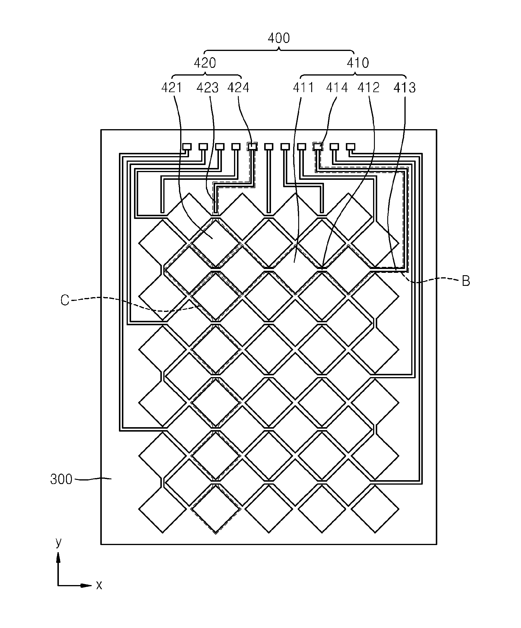
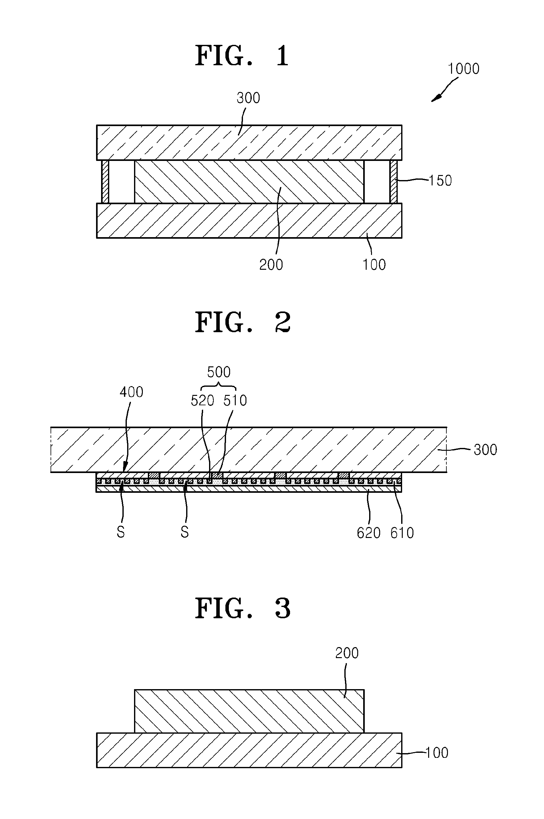
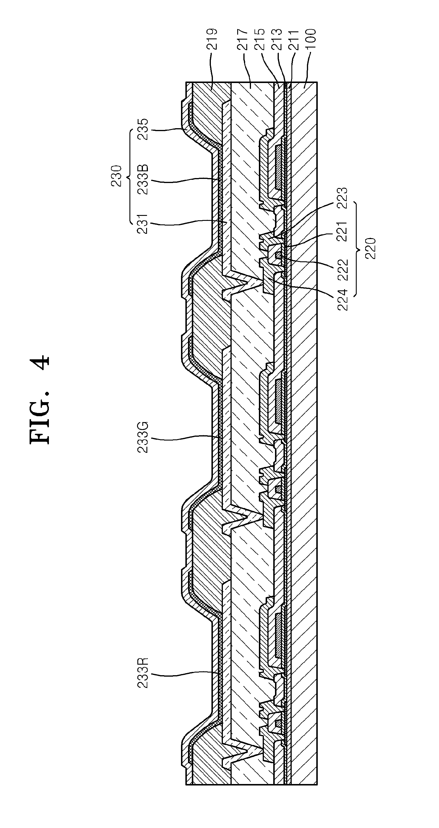
FIG. 1 is a cross-sectional view of a display apparatus 1000 according to an embodiment of the present invention. FIG. 2 is a magnifie...


PUM


Abstract

A display apparatus having an improved optical efficiency and a touch panel function, the display apparatus including a substrate; a display unit formed on the substrate and including a plurality of pixels; an encapsulation substrate disposed facing the display unit to encapsulate the display unit; an electrostatic capacitive pattern layer formed on the encapsulation substrate; and a black matrix layer formed between the substrate and the encapsulation substrate, and disposed to surround the plurality of pixels, wherein the plurality of pixels are disposed to correspond to the electrostatic capacitive pattern layer.

Description

CROSS-REFERENCE TO RELATED APPLICATIONSThis application claims the benefit of Korean Patent Application No. 10-2009-0072401, filed Aug. 6, 2009, in the Korean Intellectual Property Office, the disclosure of which is incorporated herein by reference.BACKGROUND1. FieldAspects of the present invention relate to a display apparatus, and more particularly, to a display apparatus having an electrostatic capacitive-type touch panel function.2. Description of the Related ArtRecently, the use of portable thin flat display apparatuses has increased considerably. Also, research has been conducted to obtain a thin flat display apparatus having a touch panel function. By having the touch panel function, a display apparatus can perform an input function in which a user touches a panel surface of the display apparatus with a finger or a pen.Research has been conducted on display apparatuses having an internal electrostatic capacitive-type touch panel function. However, due to a structure of the di...

Claims


Application Information

Patent Timeline
Patent Type & Authority Applications(United States)
IPC IPC(8): G06F3/044H01J9/00
CPCG06F3/044G06F2203/04111H01L51/5284G06F3/0443G06F3/0446H10K59/8792H10K59/873G06F3/0412G06F3/0448G06F2203/04107H10K50/865
Inventor KIM, EUN-AH
Owner SAMSUNG DISPLAY CO LTD
Learn More