Thermoacoustic device

a thermoacoustic device and metal material technology, applied in the direction of electro-electrothermic-effect transistors, vacuum evaporation coatings, coatings, etc., can solve the problems of sound wave generation, inability to achieve a smaller and inability to achieve small heat capacity per unit area of metal slices

Active Publication Date: 2011-02-10
TSINGHUA UNIV +1
View PDF81 Cites 15 Cited by
  • Summary
  • Abstract
  • Description
  • Claims
  • Application Information

AI Technical Summary

Problems solved by technology

The heat in the medium causes thermal expansion and contraction, and produces pressure waves in the surrounding medium, resulting in sound wave generation.
However, a suspending metal slice with thickness smaller than 7×10⁻⁵ centimeter (cm) is difficult...

Method used


Image

  • Thermoacoustic device
  • Thermoacoustic device
  • Thermoacoustic device

Examples


Embodiment Construction

[0012]The disclosure is illustrated by way of example and not by way of limitation in the figures of the accompanying drawings in which like references indicate similar elements. It should be noted that references to “an” or “one” embodiment in this disclosure are not necessarily to the same embodiment, and such references mean at least one.

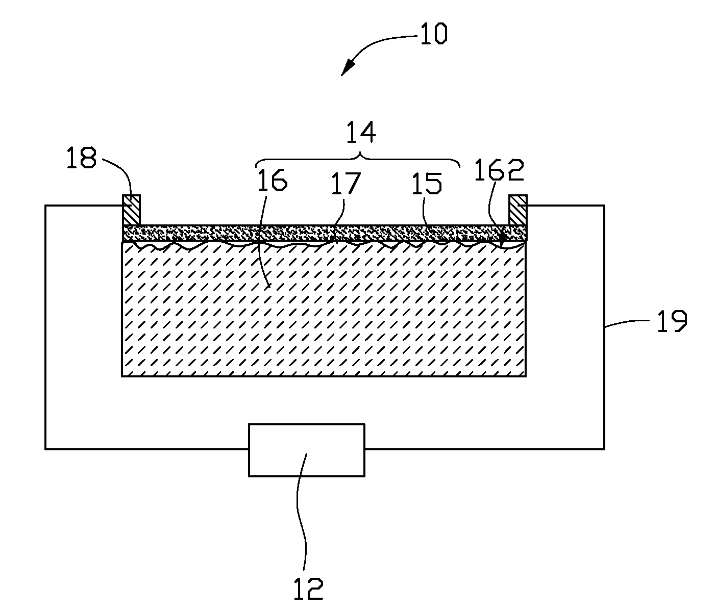
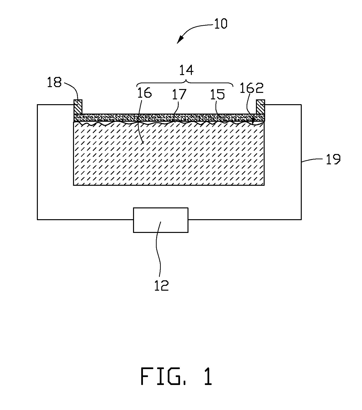
[0013]Referring to FIG. 1, a thermoacoustic device 10 of an embodiment includes a signal input device 12, an acoustic element 14, and at least two electrodes 18.

[0014]The acoustic element 14 includes a substrate 16, a plurality of microstructures 17, and a metal film 15. The substrate 16 has a surface 162. The microstructures 17 are disposed on the surface 162. The metal film 15 is disposed on the plurality of microstructures 17. The electrodes 18 are spaced from each other and electrically connected to the metal film 15 and the signal input device 12. The electrodes 18 are used for inputting electrical signals into the acoustic element 14. The e...


PUM

PropertyMeasurementUnit
Thicknessaaaaaaaaaa
Diameteraaaaaaaaaa
Areaaaaaaaaaaa

Abstract

The present invention relates to a thermoacoustic device that includes an acoustic element. The acoustic element includes a substrate, a plurality of microspaces, and a metal film. The metal film is located above the substrate. A plurality of microspaces is defined between the substrate and the metal film. The metal film is partially suspended above the substrate.

Description

CROSS-REFERENCE TO RELATED APPLICATIONS[0001]This application claims all benefits accruing under 35 U.S.C. §119 from China Patent Application No. 200910109570.3, filed on Aug. 7, 2009, in the China Intellectual Property Office.BACKGROUND[0002]1. Technical Field[0003]The present disclosure relates to thermoacoustic devices, and particularly to a metal material based thermoacoustic device.[0004]2. Description of Related Art[0005]A thermophone based on the thermoacoustic effect was created by H. D. Arnold and I. B. Crandall (H. D. Arnold and I. B. Crandall, “The thermophone as a precision source of sound”, Phys. Rev. 10, pp 22-38 (1917)). The thermophone uses a platinum strip with a thickness of 7×10⁻⁵ cm as a thermoacoustic element. When signals are input into the platinum strip, heat is produced in the platinum strip according to the variations of the signal and / or signal intensity. Heat is propagated into the surrounding medium. The heat in the medium causes thermal expansion and co...

Claims


Application Information

Patent Timeline
IPC IPC(8): H04R25/00
CPCY10T29/49126Y10T29/49155C23C14/0005H04R23/002
Inventor LIU, LIANGCHEN, ZHUOLIU, KAIFENG, CHENJIANG, KAI-LIFAN, SHOU-SHAN
Owner TSINGHUA UNIV
Why Eureka
Try Eureka