Power supply system

a power supply system and power supply technology, applied in the direction of lighting and heating apparatus, instruments, greenhouse gas reduction, etc., can solve problems such as power transmission loss, and achieve the effect of effectively utilizing surplus electricity

Active Publication Date: 2011-02-10
HONDA MOTOR CO LTD
View PDF6 Cites 34 Cited by
  • Summary
  • Abstract
  • Description
  • Claims
  • Application Information

AI Technical Summary

Benefits of technology

[0008]An object of this invention is therefore to overcome the foregoing problem by providing a power supply system that...

Problems solved by technology

However, since the system in the reference transmits the surplus electricity back to the comm...

Method used


Image

  • Power supply system
  • Power supply system
  • Power supply system

Examples


Embodiment Construction

[0015]A power supply system according to an embodiment of the invention will now be explained with reference to the attached drawings.

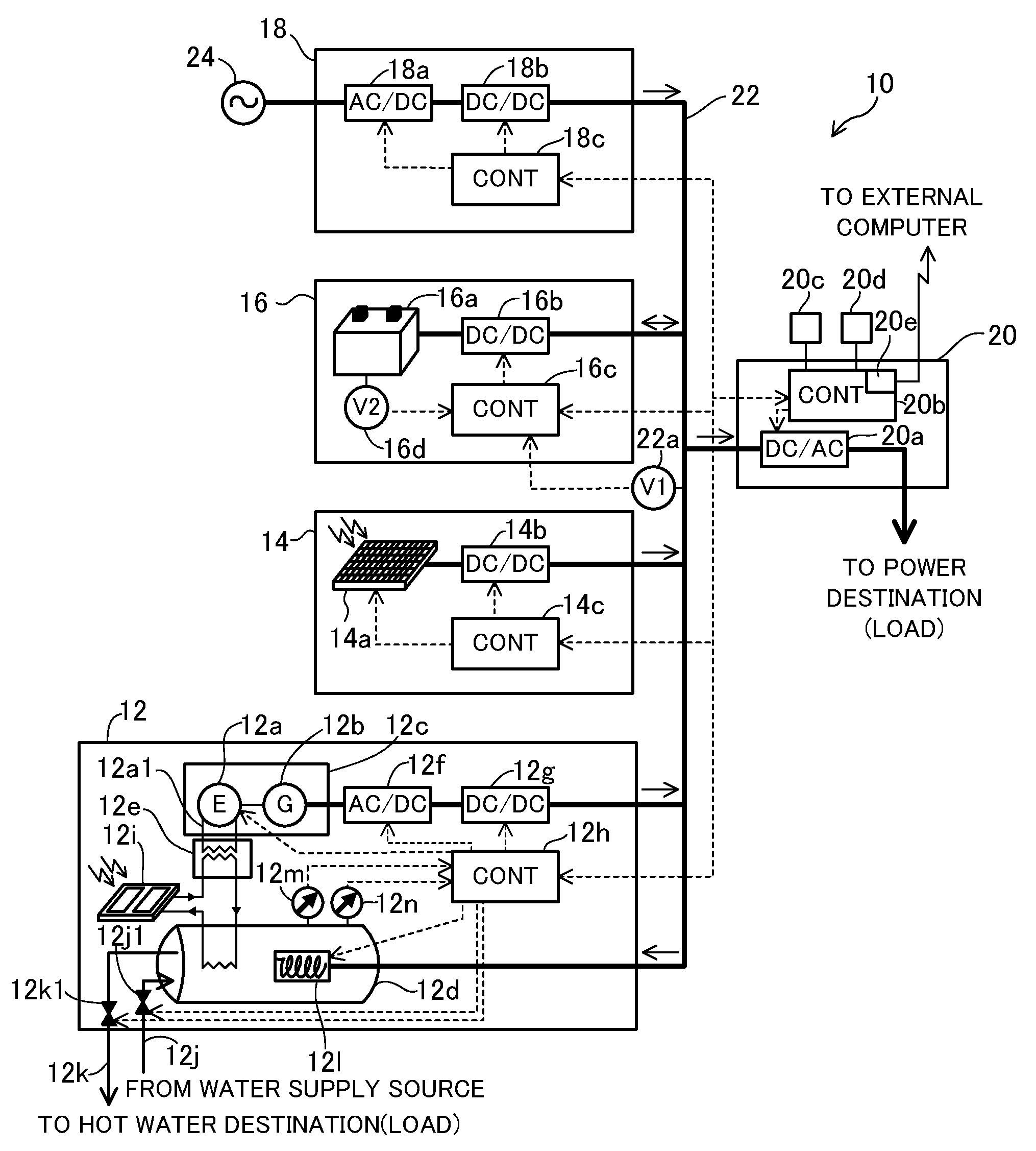
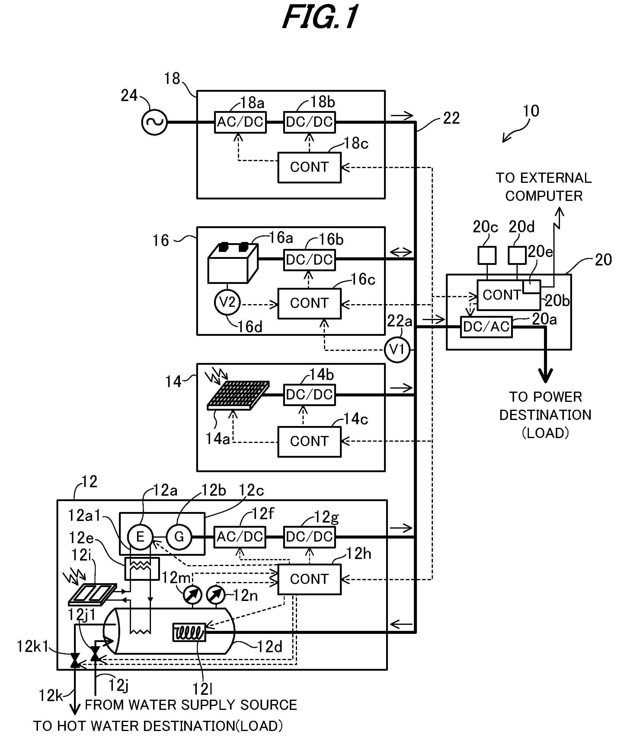
[0016]FIG. 1 is a schematic view giving an overall view of a power supply system according to an embodiment of this invention. In the drawing, thick solid lines indicate flow of electric power, broken lines signal lines, and thin solid lines flow of liquid such as (hot) water to be supplied and heating medium.

[0017]In FIG. 1, reference numeral 10 designates the power supply system. The power supply system 10 comprises a cogeneration unit 12, natural energy generation unit 14, storage unit 16, commercial power unit 18 and power supply unit 20 and also a DC power bus 22 for connecting the foregoing units. The system 10 is a distributed power supply system installed near a place where power is needed, e.g., an individual residence like house.

[0018]The cogeneration unit 12 is equipped with a main body 12c having an internal combustion engine (denoted “E” ...


PUM


Abstract

In a power supply system (10) having a cogeneration unit (12) equipped with an internal combustion engine (12a) and a generator (12b) to generate power to be supplied to a power destination and hot water to be supplied to a hot water destination, there are provided with a natural energy generation unit (14) that generates power with natural energy, a power supply unit (20) that receives the power generated by the generator and natural energy generation unit to supply the received power to the power destination; a voltage detector (22a) that detects voltage (V1) of the power flowing through an connecting bus (22), and an electric heater (12l). The power supply unit (20) controls operation of the electric heater based on the detected connecting bus power voltage (V1), thereby effectively utilizing surplus electricity without transmitting back it to a commercial power source.

Description

BACKGROUND OF THE INVENTION[0001]1. Field of the Invention[0002]This invention relates to a power supply system, particularly to a distributed power supply system installed at an individual residence to cover power demand of the residence.[0003]2. Description of the Related Art[0004]A distributed power supply system, i.e., a power supply system of distributed generation (also called on-site generation) is installed near a place where electric power is needed to generate and supply power thereto. Since the supplied power is consumed at the same location as the place it is generated, the system is superior because the power transmission loss can be suppressed. Such a distributed power supply is taught by, for example, by Japanese Laid-Open Patent Application No. 2003-339118.[0005]In the system disclosed in the reference, a DC bus is connected to a wind-power generation unit and photovoltaic generation unit (power generation unit) and to a load (power destination) to supply power gener...

Claims


Application Information

Patent Timeline
IPC IPC(8): G06F1/28G06F1/26
CPCF24J2/00H02J3/14H02J3/32H02J3/383Y02E10/566Y02E20/14Y02E70/30Y04S20/222Y02E10/563Y02B70/3225H02J2300/10H02J2300/22H02J2300/24H02J3/381F24S20/00Y02E10/56Y02E10/40H02J2310/58H02J3/46
Inventor KANAI, YASUSHI
Owner HONDA MOTOR CO LTD
Why Eureka
Try Eureka