Air sampling tube

a technology of air sampling and air sampling tube, which is applied in the direction of instruments, mechanical equipment, transportation and packaging, etc., can solve the problems of increasing installation and inspection effort, compromising coating protective integrity, and not only wasteful of tubing material

Active Publication Date: 2011-02-17
AIR PRODS & CONTROLS
View PDF3 Cites 7 Cited by
  • Summary
  • Abstract
  • Description
  • Claims
  • Application Information

AI Technical Summary

Benefits of technology

[0007]An air sampling tube is provided that assures proper axial positioning of tubular section apertures and includes a first tubular section having a sidewall defining a tube interior and a tube exterior and at least one aperture providing air communication therebetween. At least one rotationally asymmetric joining element is associated with an end of the first tubular section or a coupler secured to the tubular section end. A component is also provided having a component end with complementary tab or complementary groove to the at least one rotationally asymmetric joining element to only form a complete engagement directly with the first tubular section or the intermediate coupler in a single rotational orientation.

Problems solved by technology

This approach is not only wasteful of tubing material, but also requires field work to cut the tubing, and presents logistical problems associated with the transport and handling of tubing having a length of, for example, 5 feet.
Regardless of construction, periodically perforated tubing is prone to hole fouling associated with particulate in the air handling system and in the instance of galvanized steel tubing the hole formation compromises coating protective integrity.
The custom nature of assembly of an air sampling tube poses a problem of assuring proper hole directionality about a tube axis.
This rotational symmetry increases both installation and inspection effort.

Method used


Image

  • Air sampling tube
  • Air sampling tube
  • Air sampling tube

Examples


Embodiment Construction

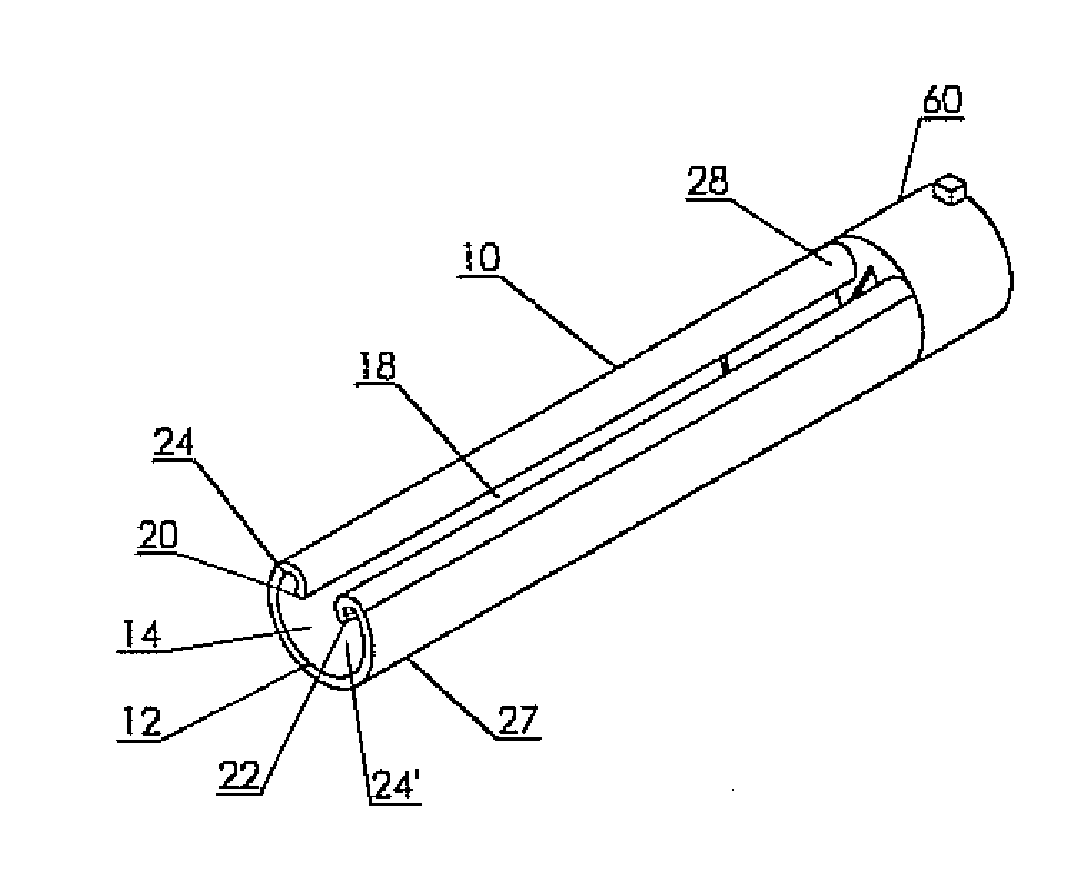
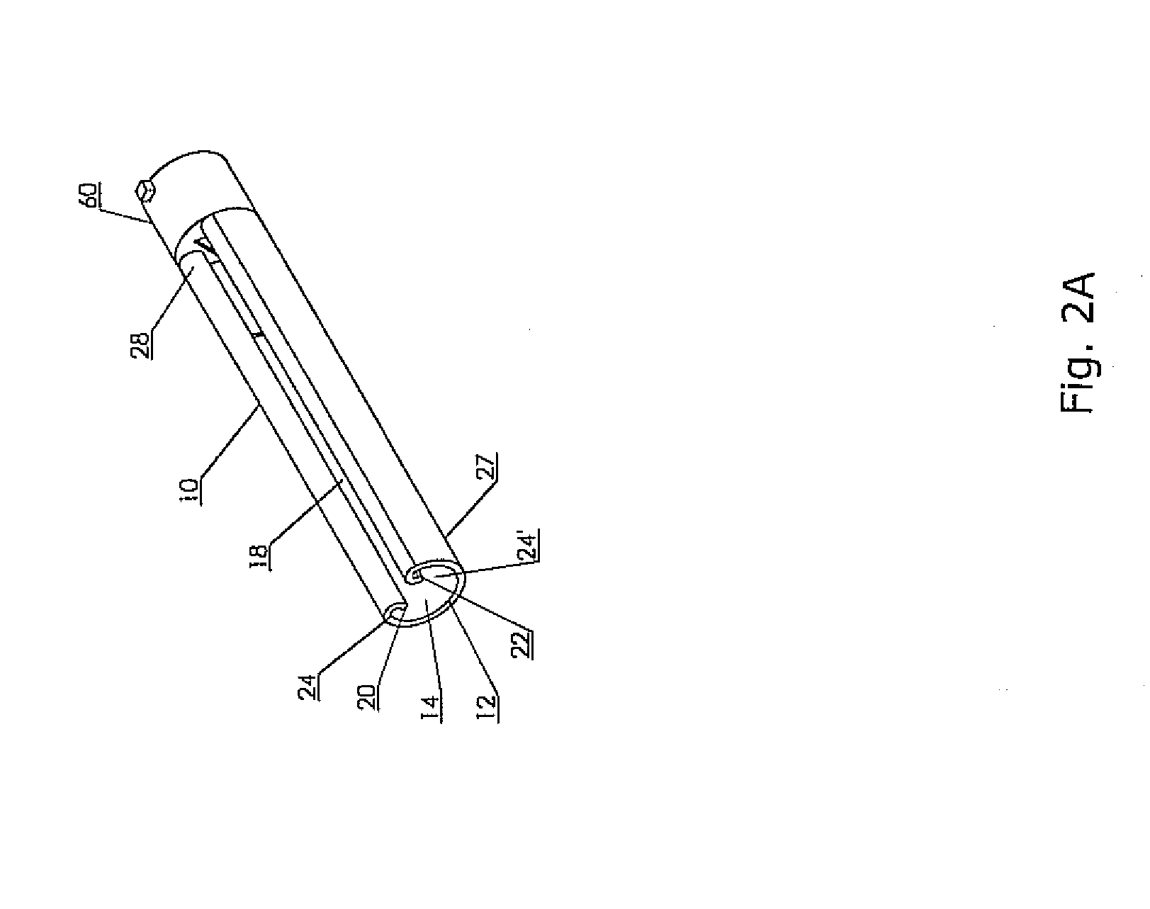
[0019]The present invention has utility as an air sampling tube to draw a continuous aliquot of air from an air handling system to convey the aliquot to a housing containing an air sampling sensor. The present invention can address a number of limitations found in conventional air sampling tubes, and the inventive improvements include assurance of directionality of an air instance aperture within a tubular section of an air sampling tube; superior mechanical strength and air flow characteristics of a tubular section; modular assembly; and a choke allowing for the visual confirmation of aperture directionality without resort to movement of a tubular section of the air sampling tube. Each of these attributes of an inventive tube is operative independent of the others. An additional attribute of an inventive air sampling tube is the ability to provide an assembler with a component kit allowing for customization of the air sampling tube without resort to tools to cut or otherwise modify...


PUM

PropertyMeasurementUnit
lengthaaaaaaaaaa
widthsaaaaaaaaaa
widthsaaaaaaaaaa

Abstract

An air sampling tube is provided that provides superior air flow, strength, and manufacturability and couples to an air sampling sensor housing. The sidewall of the tubular section has an axially extending groove. To facilitate installation and inspection, an air sampling tube is provided with a starter cap. An end cap prevents air flow through the distal end of the tube. An air sampling tube is provided that assures proper axial positioning of tubular section apertures through resort to a coupler with a rotationally asymmetric joining element. A modular kit is provided that allows for custom installation without resort to cutting or forming operations in the field.

Description

FIELD OF THE INVENTION[0001]The present invention relates in general to a tube for conveying air between a forced air supply and a housing containing a detector and in particular to a tube assuring correct alignment and providing high efficiency of air flow.BACKGROUND OF THE INVENTION[0002]The sampling of air within the air handling system of a structure is essential to the early detection of air quality dangers such as smoke or carbon monoxide. A conventional scheme for air sampling includes a housing containing a duct air quality detector such as a smoke detector, carbon monoxide detector or other types of air quality detectors such as particulate, humidity, or oxygen. A conventional duct detector housing is exposed to air from an air handling system by way of a sampling tube extending into a duct of the air handling system. The duct detector housing includes an exhaust port so as to create air flow through the detector housing. The housing exhaust port is often coupled to the duc...

Claims


Application Information

Patent Timeline
Patent Type & Authority Applications(United States)
IPC IPC(8): B65D59/06F16L55/00B65D71/00
CPCG01N2001/2285G01N1/2273
Inventor HALL, DAVID L.STOUFFER, PETERLUDWIG, JAMES E.
Owner AIR PRODS & CONTROLS
Why Eureka
Try Eureka